If Ya Don’t Know How, Don’t
I got in about 9 amplifiers, controls centers, and a few odds and ends a fellow wanted me to go through. All Seeburg of course. The first thing I put on the table was an SCC9 used in the 1972 SX-100. The fellow that brought it pointed out a resistor he had replaced that consequently smoked. Several other components, capacitors, had been replaced. The more I looked at the board the more concerned I got. One of the capacitors was a .47uf instead of a .047uf. Another had had a soldering iron dragged across it accidentally, shorting out some of the internal foils that provide the capacitance. Those got replaced. One electrolytic cap had not been replaced. All Seeburg equipment is old enough now that at least for the 1960’s and up stuff all electrolytic capacitors need to be replaced.
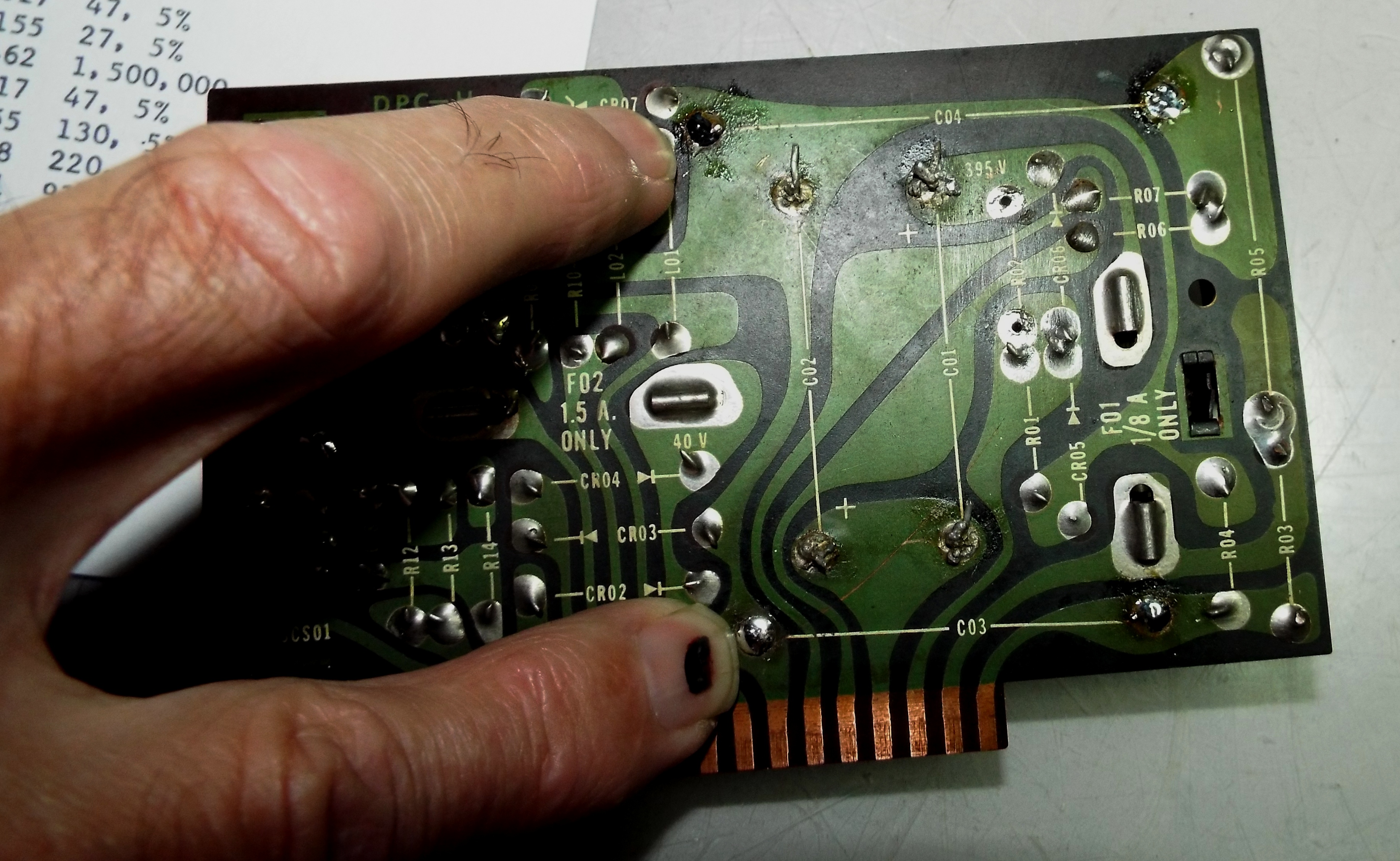
When I turned the board over all I could do was shake my head. Two capacitors had been replaced and I could immediately tell the wrong solder had been used and the guy didn’t know how to solder. The splattery looking solder joints told me the solder used was acid core instead of rosen core which is a big no-no as it will create corrosion underneath the solder joint. The joints were cold-soldered which means there was no flow and they looked gray. If you look at the picture of the board you’ll see C03 and C04 that my fingers are pointing to. The solder joints on those are smooth and shiny. Those are what a properly soldered joint should look like. Look at C02 and C01 between the two caps I soldered in to see the horror (lol) I saw. One of the leads, even with solder heaped on it was not attached to the board.
I replaced those as well. They were 15uf or microfarad at 250v. The caps the fellow had installed were huge. I’ve watched modern capacitors, and resistors, get smaller over the years. On a hunch I desoldered those two caps and tested them on my Sencore LC75. One of them measured 2.2uf instead of 15. I threw them both away and replaced with new stock.

After that I turned my attention to the resistors. I previously mentioned that resistors are getting smaller. I ordered some from Mouser some time ago and when I received them I thought I had been sent quarter watt instead of half watt. Mouser was good enough to send more as, at my insistance, they must have sent the wrong ones. They were the same size and I learned a lesson. They are quarter watt sized but have half watt capability. I never use quarter watt. I’m not going to use the modern half watts that are so small either so now any half watt resistors I order from Mouser I get one watt. They are half watt sized and look normal in the circuit. I don’t want some fellow to think I installed the smaller resistors. Easier to get ’em larger and then they at least look correct. There are still millions of NOS resistors out there normally sized.
But I digress. I pulled the burned resistor out. Looking at the schematic it is supposed to be be a one meg or million ohm. It is in circuit with another 1M to the two 15uf capacitors. One of which was actually 2.2uf. I checked all the other resistors on the board and found several out of tolerance. I try to hold tolerance to 10% at a minimum. In other words a 100 ohm resistor reading more than 110 ohms gets replaced. The ones I use as replacements are held to 5% tolerance.
There’s so much more to doing electronic work than just replacing capacitors. The caps in the chassis had been replaced in a manner I absolutely detest. The old caps had been snipped out and the new ones soldered to the stubs of the old leads. Electrically, if it is a good solder joint, it is just as good but looks like crap. So amateurish. These two in the chassis were just like the rest-wrong solder, cold solder joints. I replaced them both properly which means attaching the leads to the posts instead of stubby leads.
I get why people try to do this work themselves. They want to save money. In the long run it will cost more when done improperly. I’ve seen too many amps that had new components soldered in to stubby leads and were brought to me because they didn’t work. I then have to double-check their work before I can start troubleshooting. Do the caps go to the right spots? Were the correct sized caps used? In essence checking someone’s work is troubleshooting. And it is a pain in the butt. It takes 2-3 times the amount of work to troubleshoot one of these. It would have been quicker just to have me recap the amp in th efirst place. Bring a cap kit, I’ll install your caps.
If you want to learn, learn how to solder first even if you have to take a night course or online. Learn the proper solder ( 60/40 tin/lead). Desoldering techniques and equipment. How to check resistors. They have a color code that tells you what value they are. The size means wattage. Learn the color code or get a chart. Learn how to use a volt/ohm meter. Reading schematics is tougher. They’re full of symbols but only a few. And so full of information. They are the road map for the unit be it an amp or board. Use Google. Learn the very basics of electronics. At least what ground is.
And if you don’t know how, don’t.
