The Tedious Stuff
It is quite a feeling of accomplishment when I finish a restoration on a jukebox that has been sitting dirty and neglected for who knows how many years. It’s a lot of work that takes in the smallest details. Much of it is repetitive work such as the STD4 that is currently mostly working. The tedious details are in the sorting out that’s done to get from point A to point B to the finish line. The finish line being a jukebox that works 100%.
With a clean mechanism in place and a DCC1 that, while not correct for the box, will work I made the first selection on this 1977 STD4 juke known as the Mardi Gras in who knows how long. Or at least tried. The first digit light was the only one that would come on no matter how many times I pressed the selector buttons. It only took a few minutes to determine I had a defective black box. I marked it BAD and set it in the pile to be repaired. With a refurbished black box in place once again I pressed 111. The mechanism scanned twice and stopped. The next thing I did was get down low and look at the contact block as it moved back and forth with the mechanism after pressing the Scan Start switch. Sure enough, the A side contact block switch was not swinging up far enough to touch the tormat contacts. I slowly got the left side actuator screw adjusted correctly as pointed out in the manual under “Read Out Contact Block 3″ adjustment. I had to use a 1/4” ignition wrench to get to the screw head nestled next to the gray box mount. It’s a tight fit. Sometimes I get frustrated and take the durned mount off to get better access.
Still no selections being picked up. I checked the 3M1 points with an ohmmeter and they were open. On some models it is called the 2M1. Whatever the nomenclature it will be the outermost pair of switch blades on the lower horizontal switch stack. It is part of the trip solenoid circuit and has to be closed during Scan operation. I learned years ago, the hard way naturally, about this switch. The cost to learn was about an hours of tracing out the trip solenoid circuit point by point with an ohmmeter. I was on a service call and did not have a manual with me. In those days if I didn’t fix whatever the point of service was, I didn’t get paid so I was willing to go to lengths to make a repair. It was also the last jukebox service call I made without a manual. After properly adjusting this switch I made a selection and the juke started picking up many selections. This is normal. The individual contacts on a tormat can hold a charge for a surprisingly long time. Many times on service calls once I got a juke picking up selections, usually by cleaning the switches and tormat, the jukebox would then pick up all the missed selections that had been made.
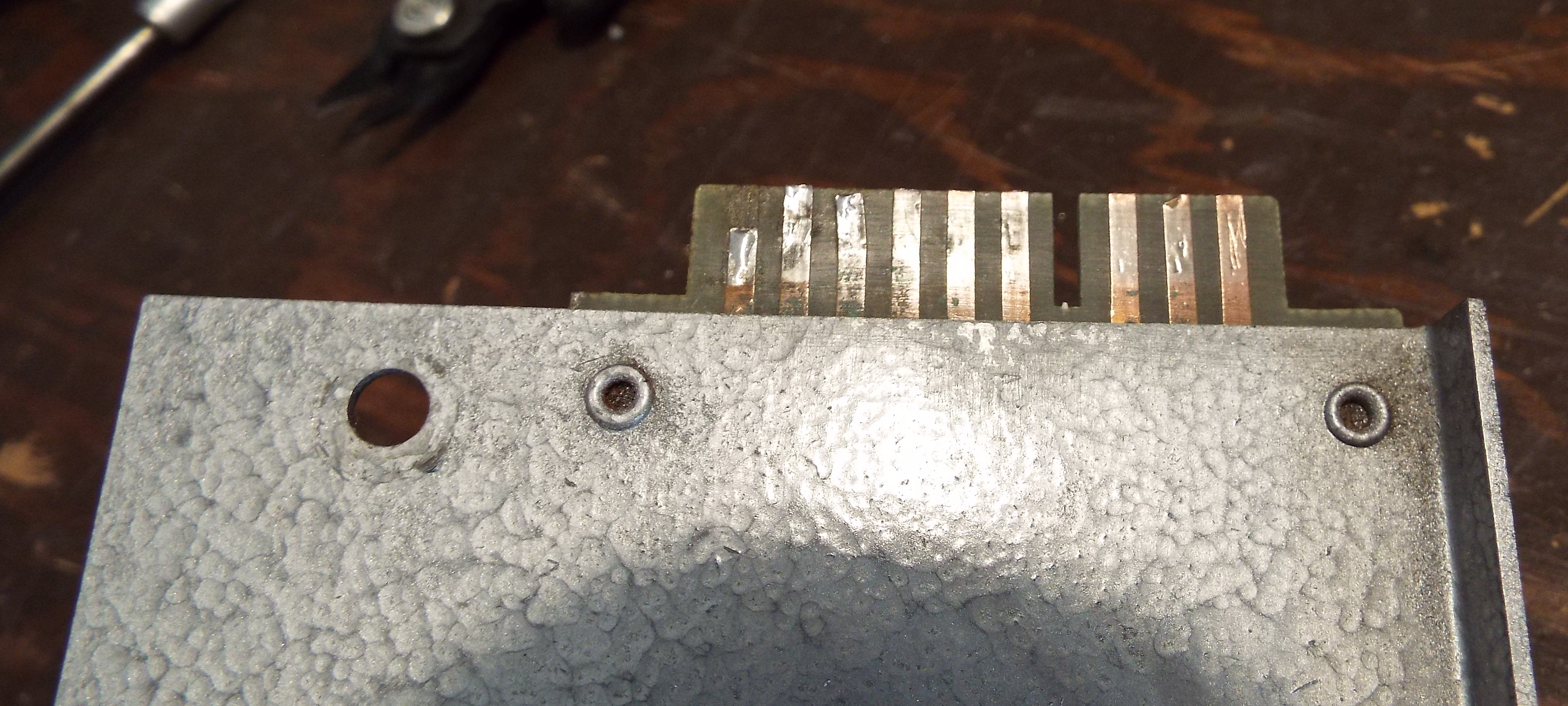
I immediately noticed that the Record Playing indicator lights were not all lighting up. Since it wasn’t working all the way I didn’t have a quick indicator if the proper selection was being made or not. No records were in the magazine as well. The top piece across the record magazine doubles as the contact plate for the selection playing wipers. I guess you could call it the track. It plugs into the system on the left and I had noted that this one has damage to its board contacts. I took a lot of time cleaning and testing lamps to ensure that all 20 indicator lamps were good. I cleaned the wipers on the pickup under the track again. I really wanted to be able to use this piece as-is and gave it every chance I could to do so. The alternative will be a lot of work. I scanned the mech several times while checking lamps. Most of them lit. I took the same piece off the Test Juke, installed it on the STD4 and all lights worked. I do not have a spare one of these and am too cheap to buy one. Especially when I can fix it. The “fix” isn’t very pretty but will work like a champ. What I will have to do is solder individual wires to the board contacts and run them to Molex connectors. After all is done I’ll neatly slather JB Weld over the board contacts to help secure the wires.
This jukebox came with a SHP1 amplifier first used in the 1971 USC1. Again, not the correct amp but it substitutes for the original SHP3 as “plug n play”. I had gone through it weeks earlier and initial testing on the bench proved it to work fine except for one small detail. The bias on the left channel would wander high after perhaps 20 minutes of playing time. Not an amp killer but something that would have to be taken care of. I had an idea that it might be the driver transistors. I had replaced the left and right bias pots which are normally the usual suspect. Before repairing the indicator track edge connector I thought I would jump back on this amp.
I changed out the driver transistors on the left channel. A couple years ago I found that the forward bias on these needs to be above .500 ma for best results. I figured the old transistors were wandering after warming up. I set the amp up on the bench, turned it on, took measurements and had excellent bias on the left channel. I set it typically low at .005-.007 millivolts. And now there was no bias reading in the right channel no matter how I adjusted the bias pot ! I quickly felt the heatsink and it was cool to the touch. The SHP1 can handle a lot more bias than the SHP3 without damage and I’ve actually blown amps while trying to rein in the bias voltage so this was a bit worrisome. I did have a SHP1 a couple years ago that did the same thing on both channels-no bias reading no matter how the pots were adjusted. It worked fine and did not heat up. I never found out why, just accepted and moved forward.
Still, I was curious and a bit determined to get the right channel bias straightened out. I must admit I also have a very strong sense of curiosity. We all know what happened to the cat. The bias for the output transistors is measured from Test Point 1 on the heat sink to the collector or case of transistors Q5117 and Q 5127. Tony Miller detailed another way to test and set the bias by measuring the voltage drop between the base legs on each pair of driver transistors. So I set the amp upright to access the underside and started measuring and adjusting bias. Mr. Miller says the perfect bias setting is 1.6 volts. This method was working and I made sure each channel had proper biasing. However, I tried holding both leads in one hand while using the other to adjust left channel bias. As my eyes went from the leads to the meter I heard “it” milliseconds before the driver transistor literally exploded. One of the meter leads shorted the base and collector of the driver transistor I was attempting to measure. “It” is a funny sound hard to describe. I’ve heard “it” several times as the current in a device, in this this case a transistor, quickly overheats and bursts the device. It was spectacular in a tiny way. The whole face of the transistor blew off. I felt small bits hit me in the face and was thankful I was wearing glasses.
Back to tedious. I now had to troubleshoot the amp to find the extent of the damage. It was a lot. One output transistor and both its driver transistors. I took the heatsink off to check the large “protection” resistors, one for each of the output transistors. They were OK. I checked the bias circuit for that side. The SHP1 uses a heatsinked transistor versus diodes in the SHP3. It was shorted out. Both its biasing resistors were way out of tolerance. That little transistor is a booger to change. But what ya gonna do? Usually the aforementioned devices are what almost always blow when an overcurrent situation arises. The three 100 ohm “protection” resistors on the driver board were fine so I didn’t go deeper into the channel. After replacing these parts I actually have a bias reading on the left channel but no sound and of course the right channel has sound but no bias reading. So I will get to delve deeper. Tomorrow. For now I’ve had all the tedium I can stand.
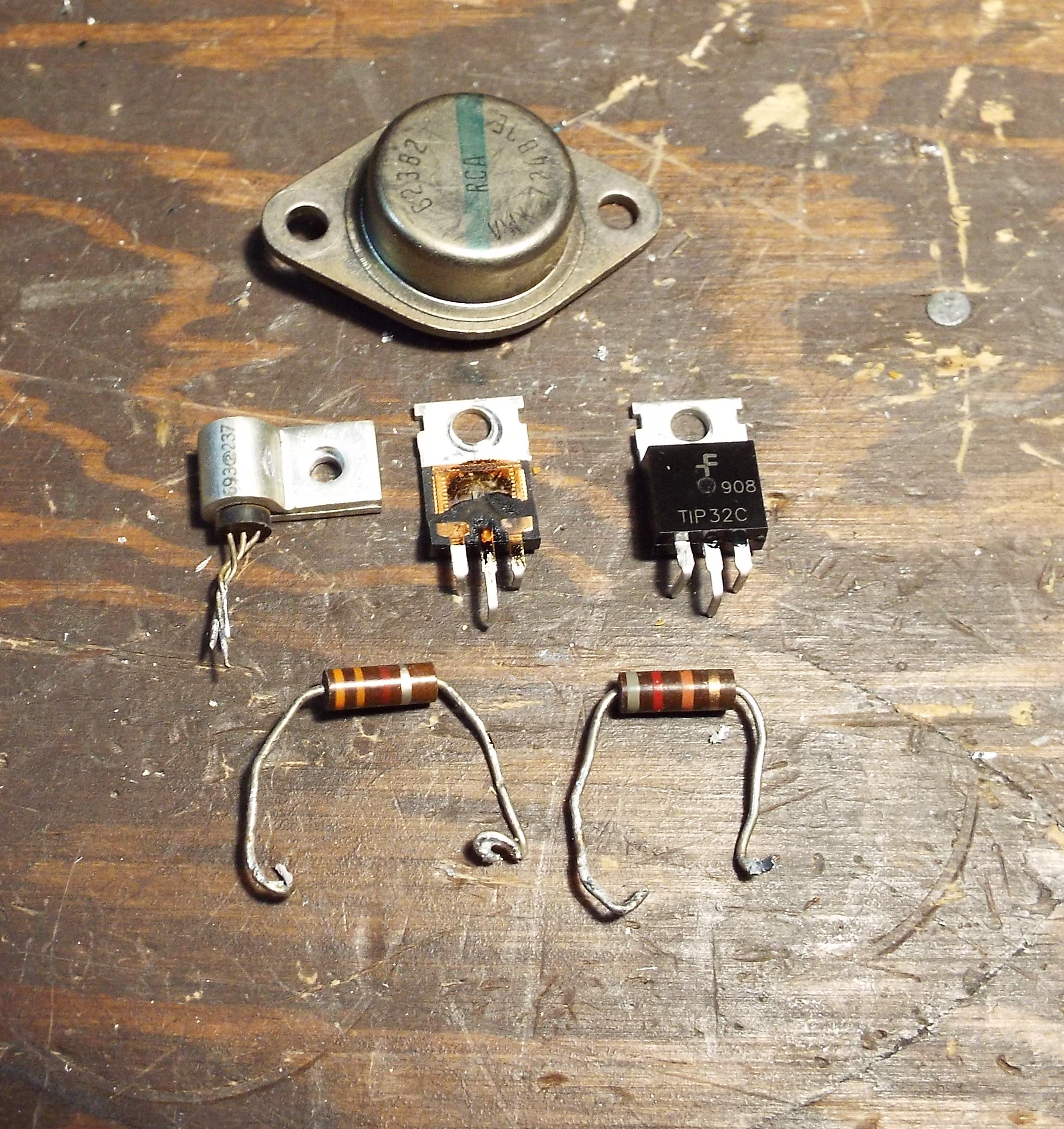
Note the black goo looking stuff on the two right side legs of the TIP32C transistor on the right. It was not far from exploding either.
