Devil…Details…Part II
This morning I started right where I left off and finished the rest of the pulse amps. I put their covers on and cleaned them up with a rag and cleaner. I had repaired Jeff’s C amplifier and when I take it back to him I’ll take the opportunity to test the pulse amps in his DS160.
I gathered up the SMC selector buttons and faceplate for re-assembly. This is ticklish. Because of the way they’re mounted I had to work with it upside down and backwards. It’s the only way to keep the springs in place. I had most of the buttons backwards because of this and finally got them all right and the darned thing mounted. Details? This piece that I just referred to actually holds the CPU and the upper titlestrip holder. It is mounted to the jukebox with four 10-32 nuts. And of course a couple of the small studs were stripped for some unfathomable reason. There is no shortcut. At that time I did not know they were 10-32. It took some experimentation with screws, gauges, and dies to find out for sure. I then used the 10-32 die to rethread the damned studs. Bolted the piece up. Bolted the CPU in. And still had an Error 80. I removed the left and right bottom screws that hold the CPU case in and could move it in and out and hear the left reset button clicking. I can only think that the studs that came with the Gen2 computer board to bolt it into the metal case are just a hair short. I have not experienced this problem with any of the half dozen Gen2’s I’ve used to date. I used six small washers on the studs to hopefully space it away far enough that the reset wouldn’t hit. I didn’t measure the thickness but I’d estimate the washers were no more than .010 thickness. And it worked. It spaced out the board just enough to give clearance between the board and the buttons.
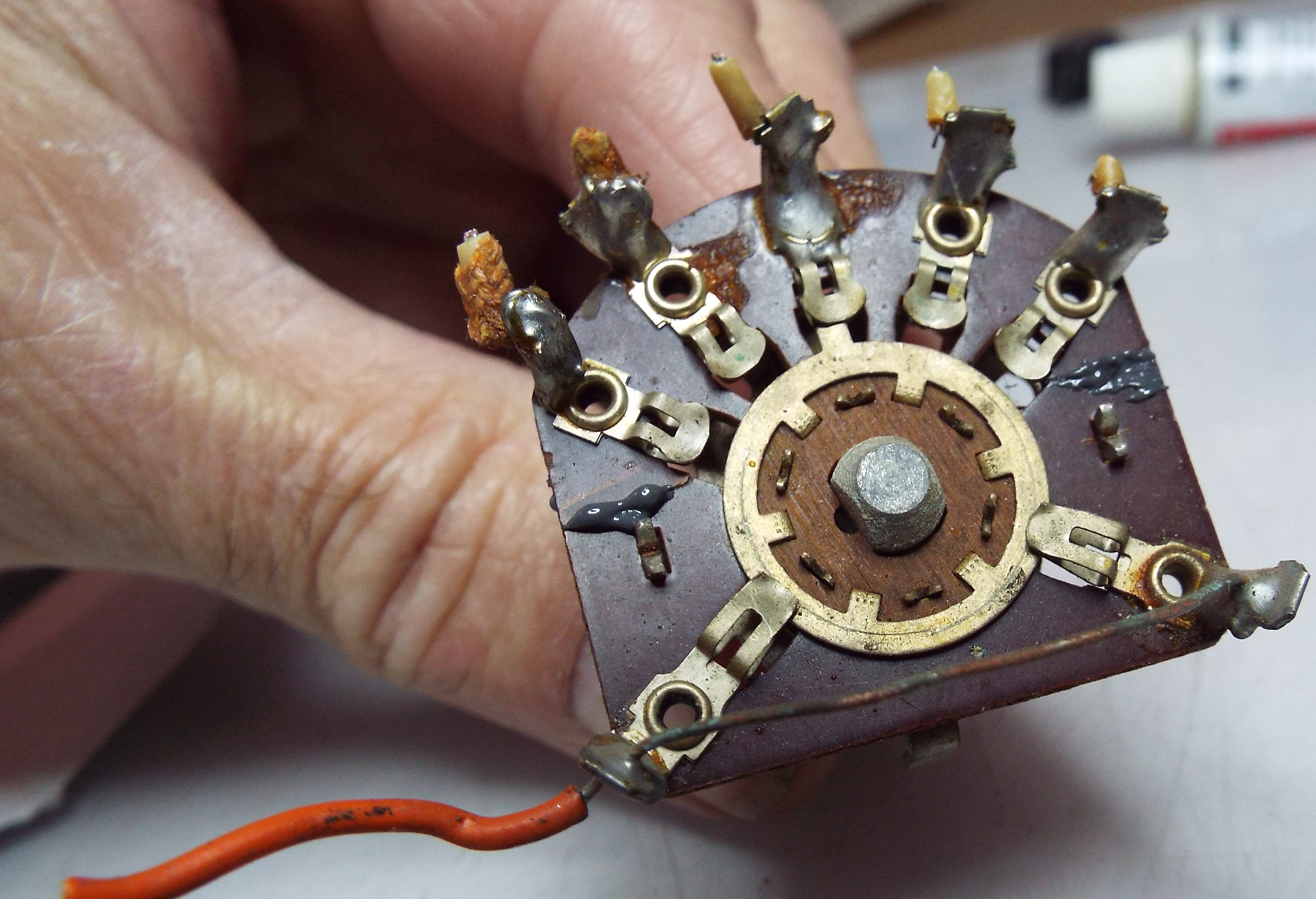
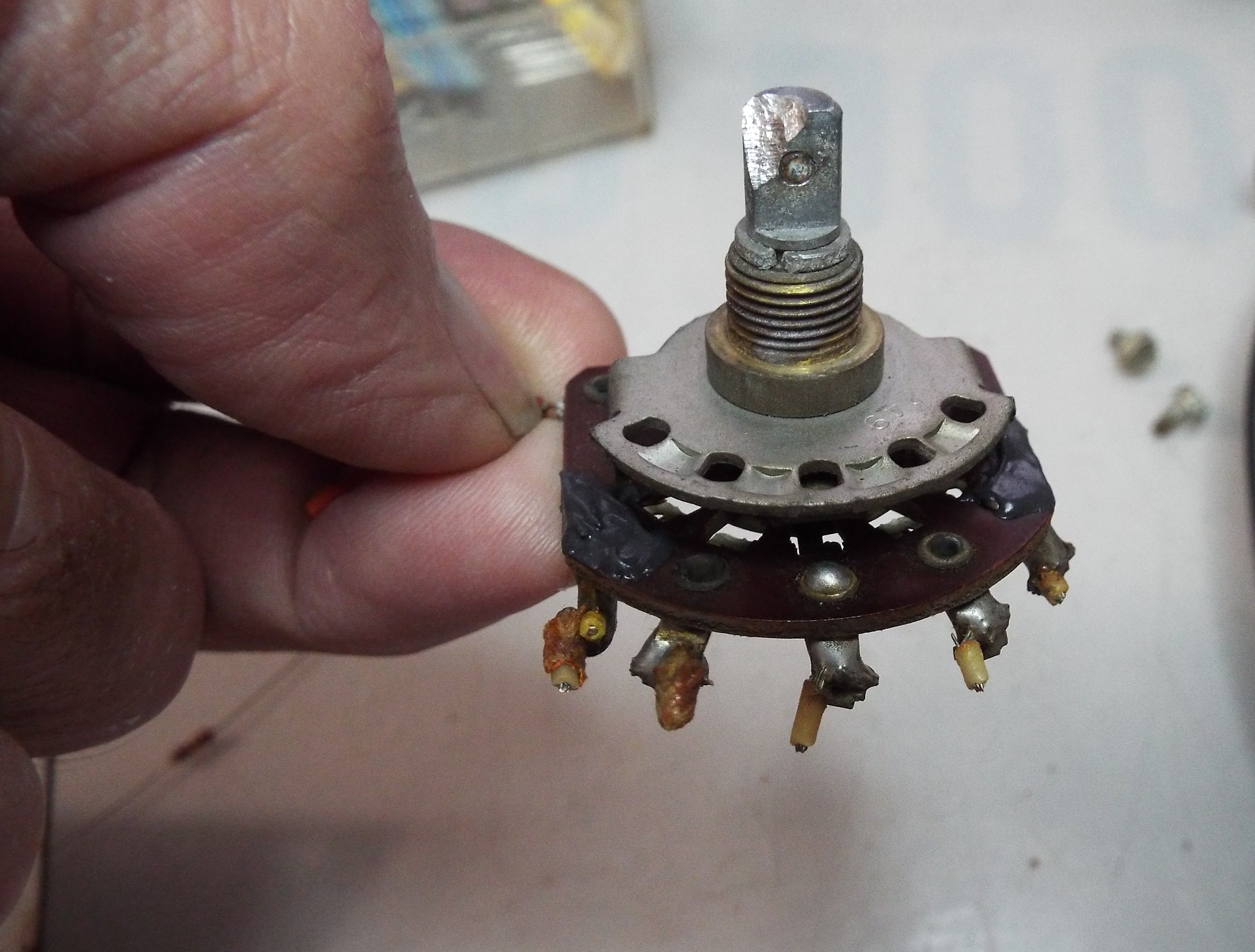
I had two broken plugs on the SHP3 amp. These get brittle from exposure to the UV rays from the fluorescent lamps and break easily. All the plastics in the SMC models are susceptible to this exposure because of the twin lamps and lack of any type of diffusion. The coin chutes get really fragile. There was other work to be done as well on this amplifier. Yesterday I picked up the pre-amp board by one of the tone control tabs and it promptly came apart. It is a minor miracle I found the two slide springs and intact at that. Using my Molex pin extractors I replaced the two plugs fairly quickly. One is a 12 pin used for the volume control. The other is a larger 6 pin used for mute/trip relay. I unsoldered the slide control, cleaned it and re-assembled the parts resoldering it back onto the board. Did the other one as well. Whenever I refurb one of these amps removing these tone controls and taking them apart for cleaning has become standard. They are nearly impossible to clean when assembled. And whoever says silver tarnish is conductible is full of bull. Onward and upward.
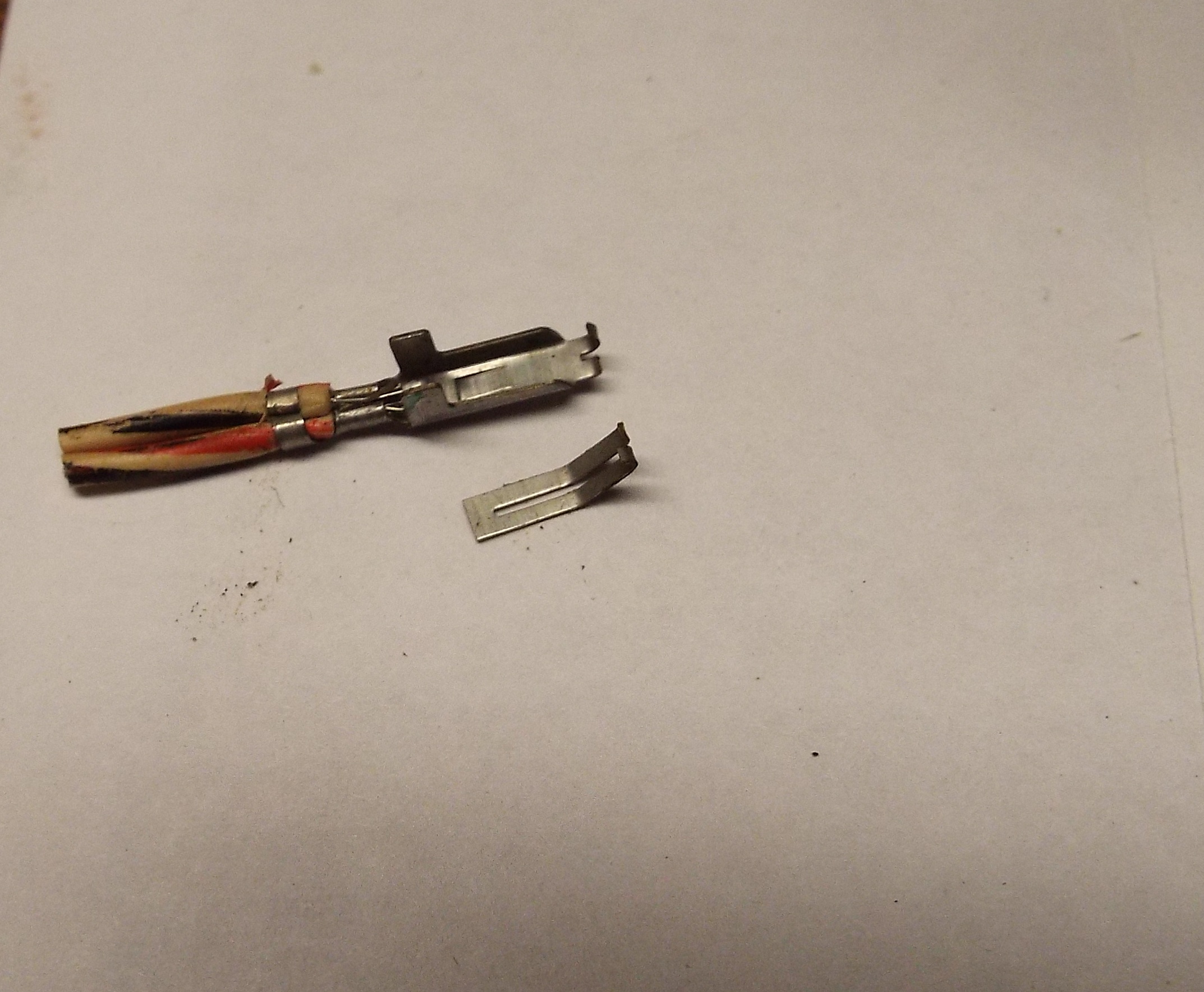
I dragged the amp back out to the bench and started examining the Molex edge connectors for the two boards. It is fairly common to have to “re-spring” the contacts. They get depressed sometimes (as we all do) and I’ll use a small diameter tool to lift each of them from underneath. Everything was going along swimmingly until one of the connectors broke in half. It was pin 1 on the pre-amp board which is Left Input. This is very unusual. There was no corrosion or any hint of something that would make this connector break. I replaced it and started looking a little harder at the rest of them. I found two that have cracks on the terminal faces. I need to go through these thoroughly and will do so tomorrow when fresh, with magnifier eyes on, poking and prodding my way along. These edge connectors have to be dependable.