The over heating problem on the SMC2 has been narrowed down to the PCC board. I swapped in a different one and an hour later the mech was still picking up a record when moving from right to left. This has been the defining test. As long as it will do that everything is fine. I spent about 30 minutes with the schematic identifying circuits that could possibly be at fault then another half hour ordering parts from Mouser Electronics. I basically ordered all the IC chips on the board times three with plenty of IC solder tail sockets plus a few tantulum capacitors and the 2N6348 triacs used in these. Just in case any other PCC board needs attention. Always replace both triacs at the same time. These IC chips were dirt cheap back in the day and still dirt cheap all less than a dollar each. There are two iterations of this PCC board. The one I’m working on is the second generation. This evening I removed U1, U6, and U10 and socketed the same. When my order arrives I’ll pop in the chips and see if I deduced correctly. On a board like this, with components as cheap as they are, it is a valid process to just “shotgun” it-or replacing all the chips at one go. I’m trying to be a little more accurate. I might learn something. The circuits affected by the chips I pulled have to do with reading the 100 side of the limit switches and also playing the B side. These are the two biggest faults shown when it overheats.
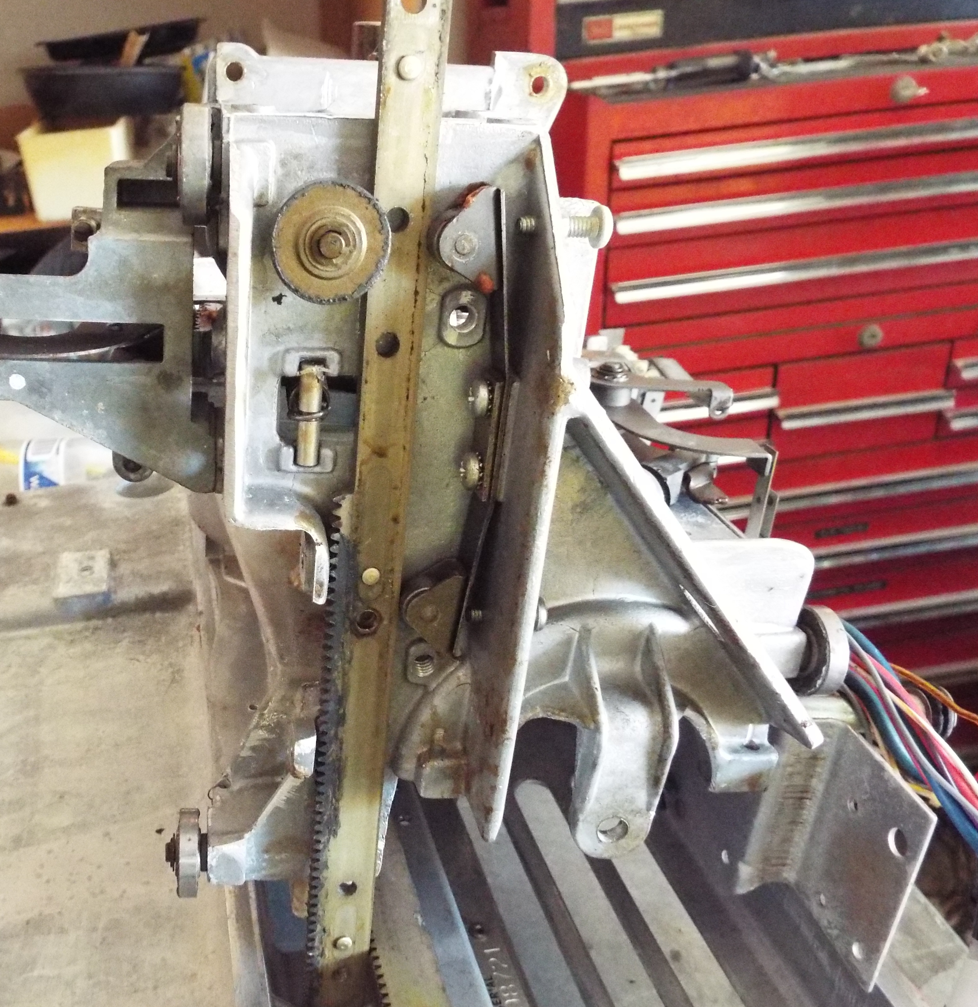
I worked on the SMC1 mechanism for about an hour and a half. The first place I start on any mech is to take it off the track and inspect and lubricate the bottom wheel and the two carriage guide roller wheels. I’ve found them brinnelled before which means the round steel wheels develop flat spots. Then the wheels slide instead of rolling. This is a result of dirty tracks caused by over oiling that attracts dirt which becomes wheel chocks. The gear tracks are two halves. I roll the mech over one half, take the screws out of the other half, and gently pry it up and off. The cable guide at front will need to be unfastened.
I found a fairly rare problem with the brake cam on this mech. I’ve only seen it once before. A more common problem are the springs on the followers breaking. The followers are no fun to change out because they are so small which makes it tough to set the spring tension and hold it in place to tighten down. One almost needs three hands. Anyway, it looks like the metal stop for one of the followers wore down. This will give a half-hearted swipe of the cartridge brush cleaner. I’ve found a few hinky things on the Stern version of the SMC that don’t have quite the quality of a Seeburg made Seeburg. My fun started when I tried to install a replacement brake cam. The roll pin went about half-way and wouldn’t go any further. I hit it as hard as I dared which then made it a booger bear to get out. I promptly shattered my 1/16 punch trying to knock the roll pin back out. A 1/8 punch is just a little too big. I did eventually get the roll pin back out. I then bevelled both ends of another roll pin, cleaned out the brake cam and camshaft holes with a file. All work I should have done the first time. I took a quick look hoping that I hadn’t bent the camshaft. They’re not difficult to replace, just tedious. This time everything went together like it should with the roll pin fully set.
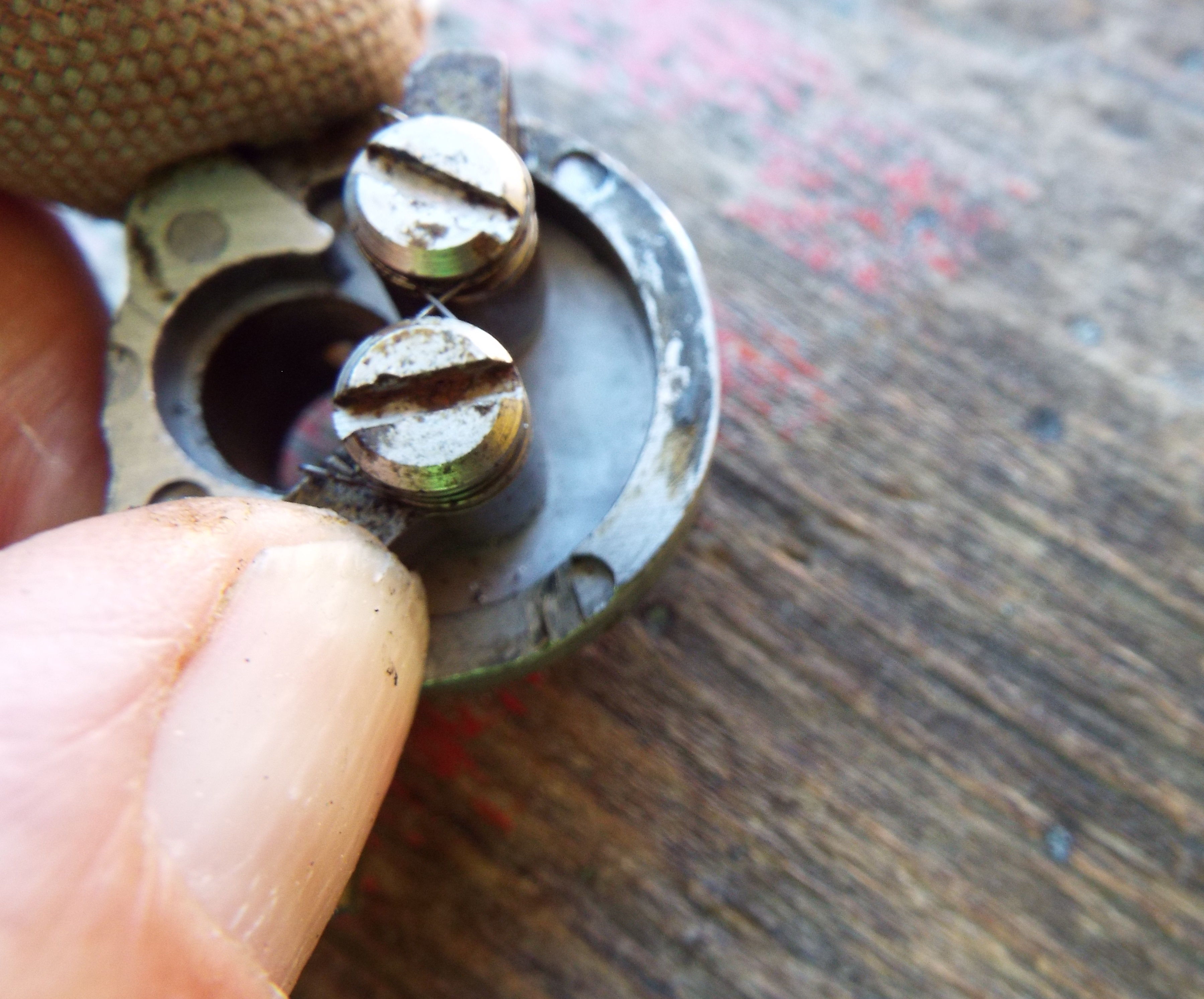
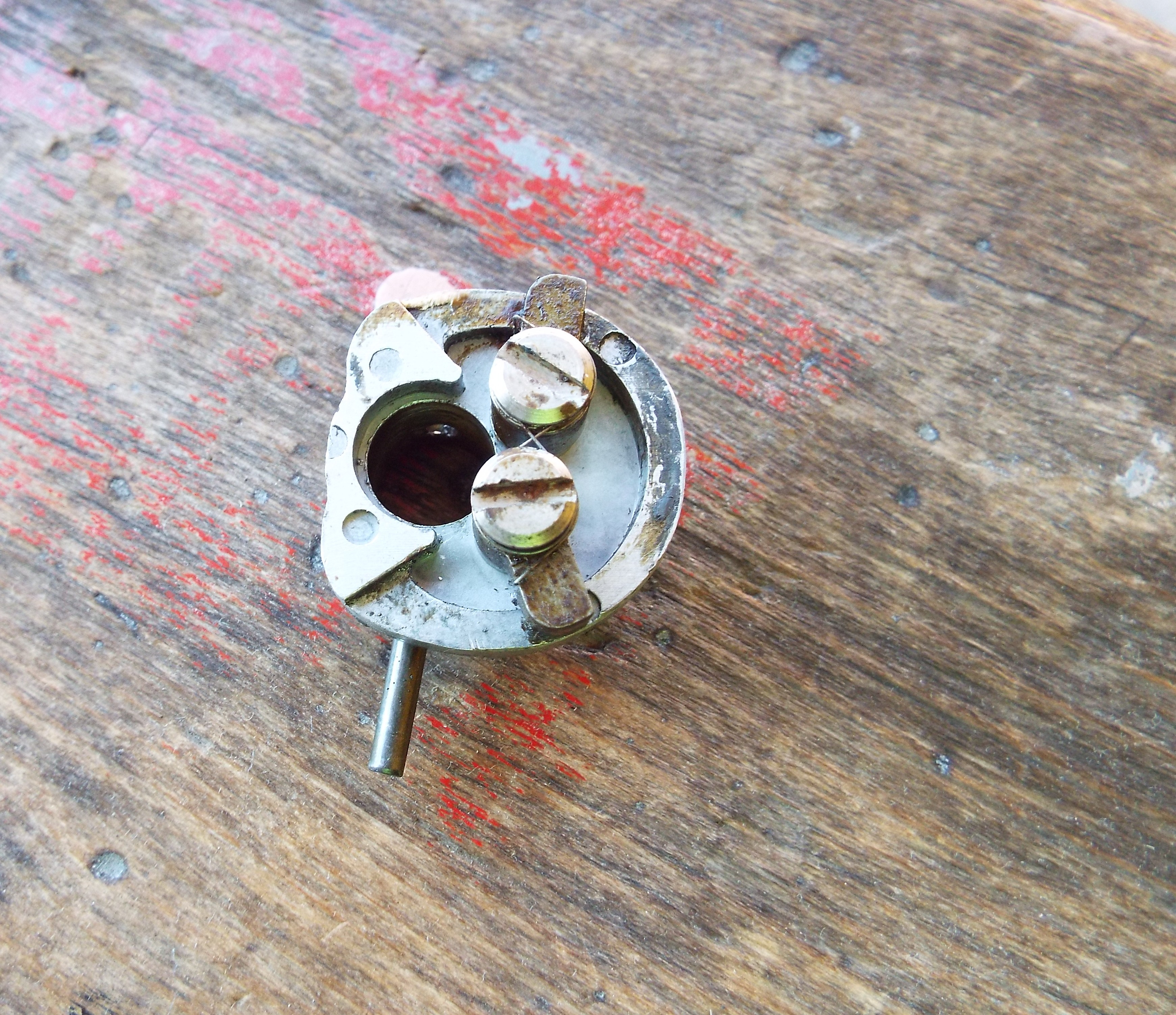
The top motor mount on the NiDec three wire motor was ruined. It got oil soaked which softens and deteriorates rubber then almost fully dried out from years in storage. I don’t have any NiDec mounts but plenty of Bodine mounts. They’re different, the Nidec motor mount inside diameter is much smaller than a Bodine. I bought a few cool adapters from Victory Glass. They’re basically a metal ring that fits on the NiDec motor taking up enough space to install the slightly larger Bodine motor mount. The ring went on the motor well with a good interference fit but its outer diameter was a tad small. The Bodine mount was too loose. I did what any good man would do-I broke out the JB Weld and after cleaning the inside steel very well epoxied the two parts together. I’ll leave it overnight and see what I have in the morning.

