You know you have a friend when he’ll let you help junk up his garage. Jeff’s garage is slap full but he will make room for one more when needed. I came across an SMC1 priced right that I couldn’t pass up and with my garage full Jeff is nice enough to let me store it there. If I ever get done with the SMC2 it’s next up.
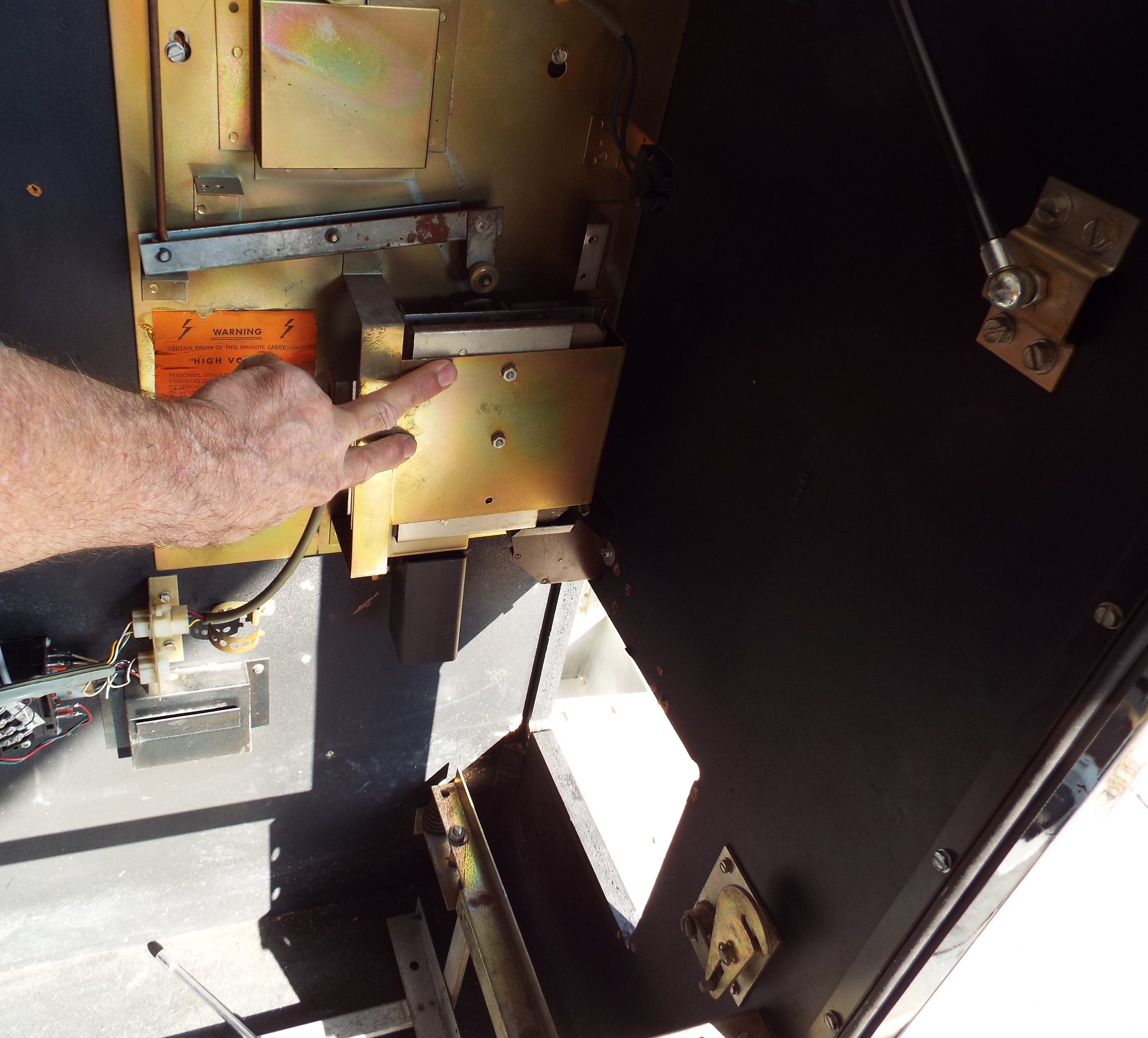
I took both SMC2 MCU’s and a PCC over to Jeff’s Saturday morning to test them in the SMC1 and see how they acted. That was quickly nixed when I saw all the wires ripped out of one of the MCU connectors. I switched gears and took that harness out, the mechanism, the CPA, and the PCC. I will have the capacity now to swap out parts now with the SMC2 to narrow the problem I’m having with it down. The mech is filthy, someone over-oiled it religiously. I’ll have to repair the harness of course.
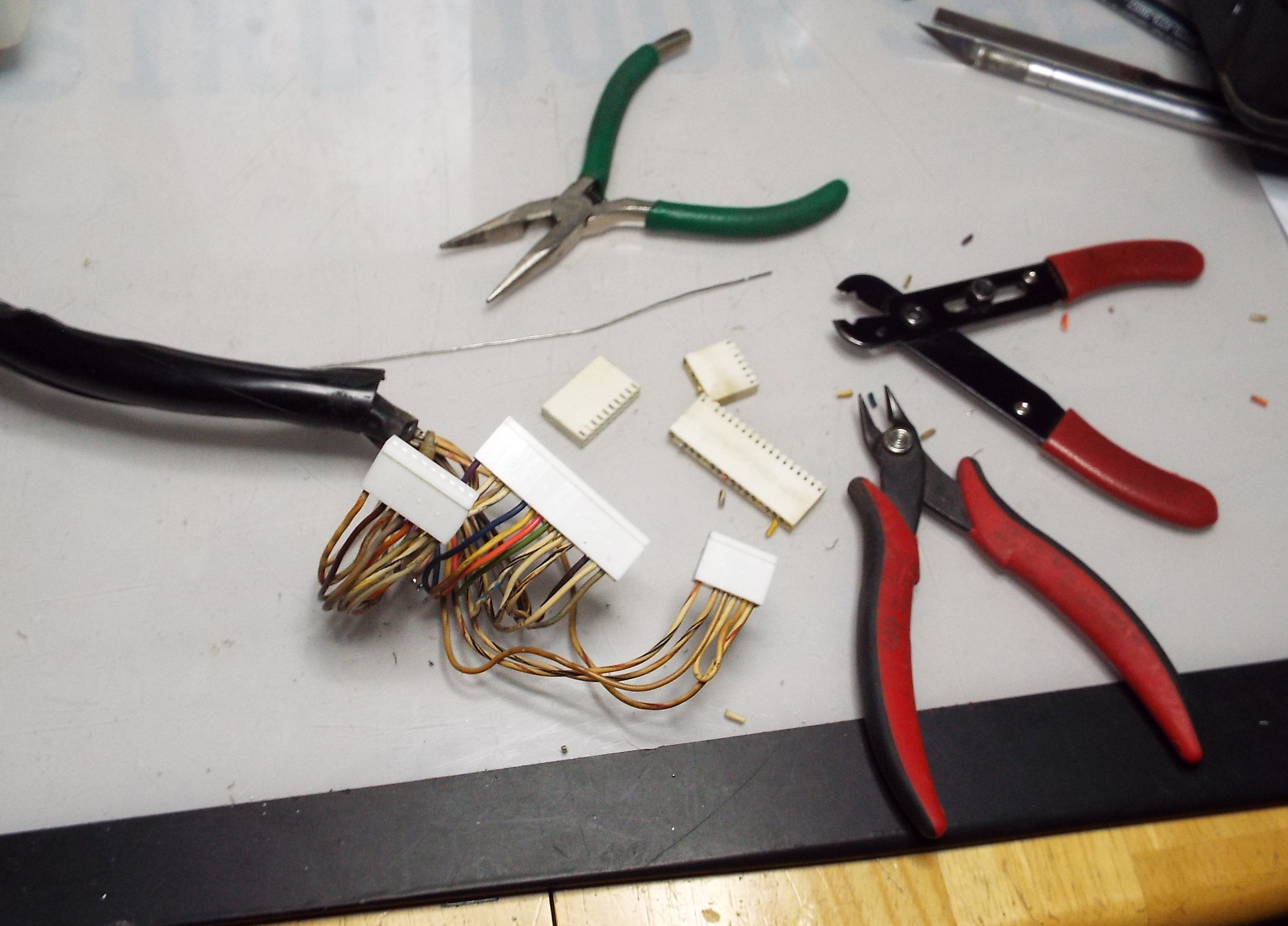
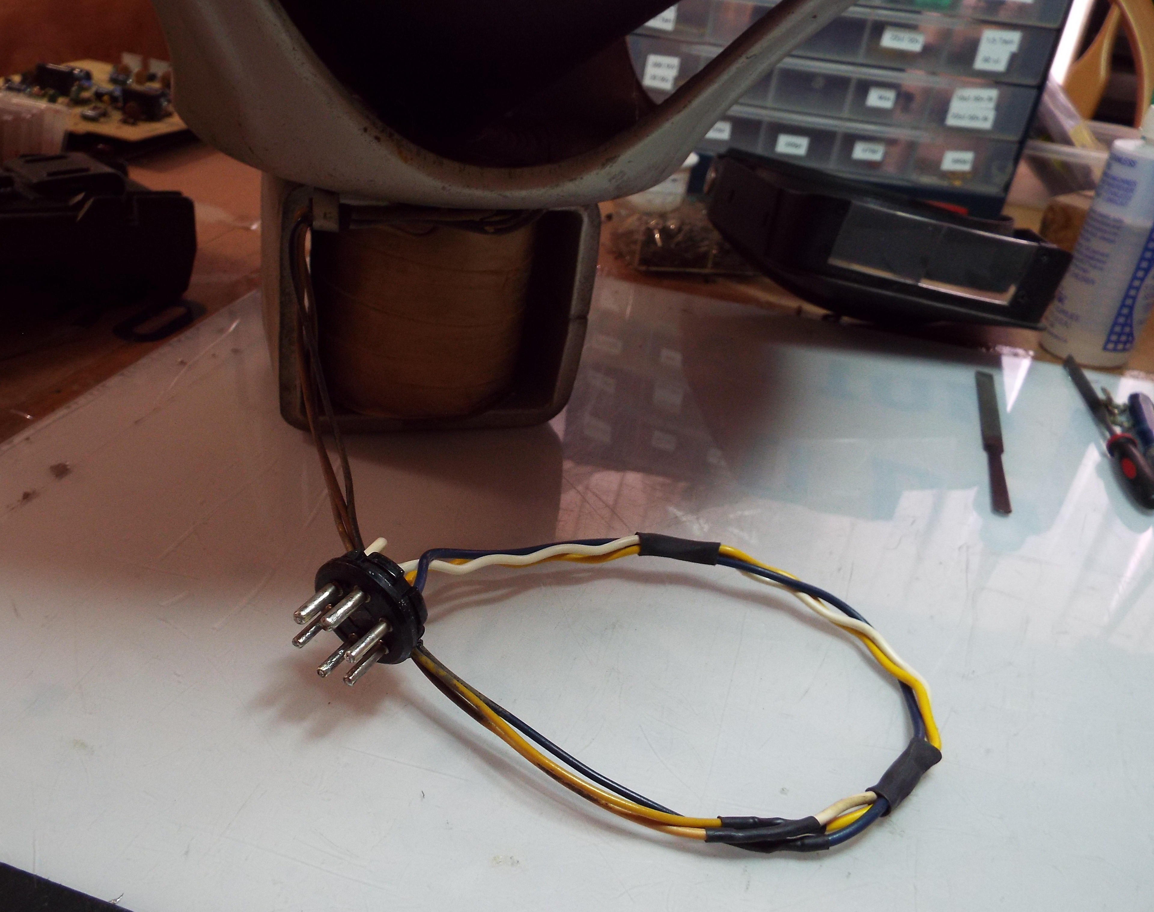
After extending the wires on a C speaker and wiring in a new plug I sat down with the SMC harness. This harness goes from the PCC to an amplifier plug-in near the coin mechanism from the mechanism, then on to the amp, the CPA, and the MCU. I’ve repaired many MCU connectors over the years. Battery acid damage usually was the reason. These SMCs would get stored with the memory batteries still in place. They would corrode and the acid travels. Just like on the old Bally pinball machines with the CPU board. There are a couple methods I use to inspect these pins. The first is for signs of corrosion. With battery acid damage it’s pretty easy-there’s green stuff. I will put a light behind the connector while holding it and look for flattened connectors from the front while peering through the connector as well. If you see one it is obvious. They have either lost their tension or broken off. I used to use the brown Bally .100 headers for the MCU but haven’t had those around for some time. Now I order the correct .100 headers from ebay and trim as needed. It took me a little over an hour to replace all three plugs and connectors. After crimping the connector I like to add a drop of solder for a bullet-proof connection.