STD Madness Part II
A quick recap: I got the mech working to my liking on the STD3 and re-installed in the juke. I had gone through the power supply board in the DCC recapping it and testing for correct voltages at the DCC test points. For grins I took the selector keypad apart, cleaned it, and tested it on the STD4. It was now time to make some selections and see what happened. From habit the first selection is always 266, this lets me know quickly that write-in and read-out are working. The mech stopped at 244. Now the madness began in earnest. It took me three weeks of working 1-3 hours a day to finally find the problem. A combination of bad luck and wrong assumptions lead me on the long path.
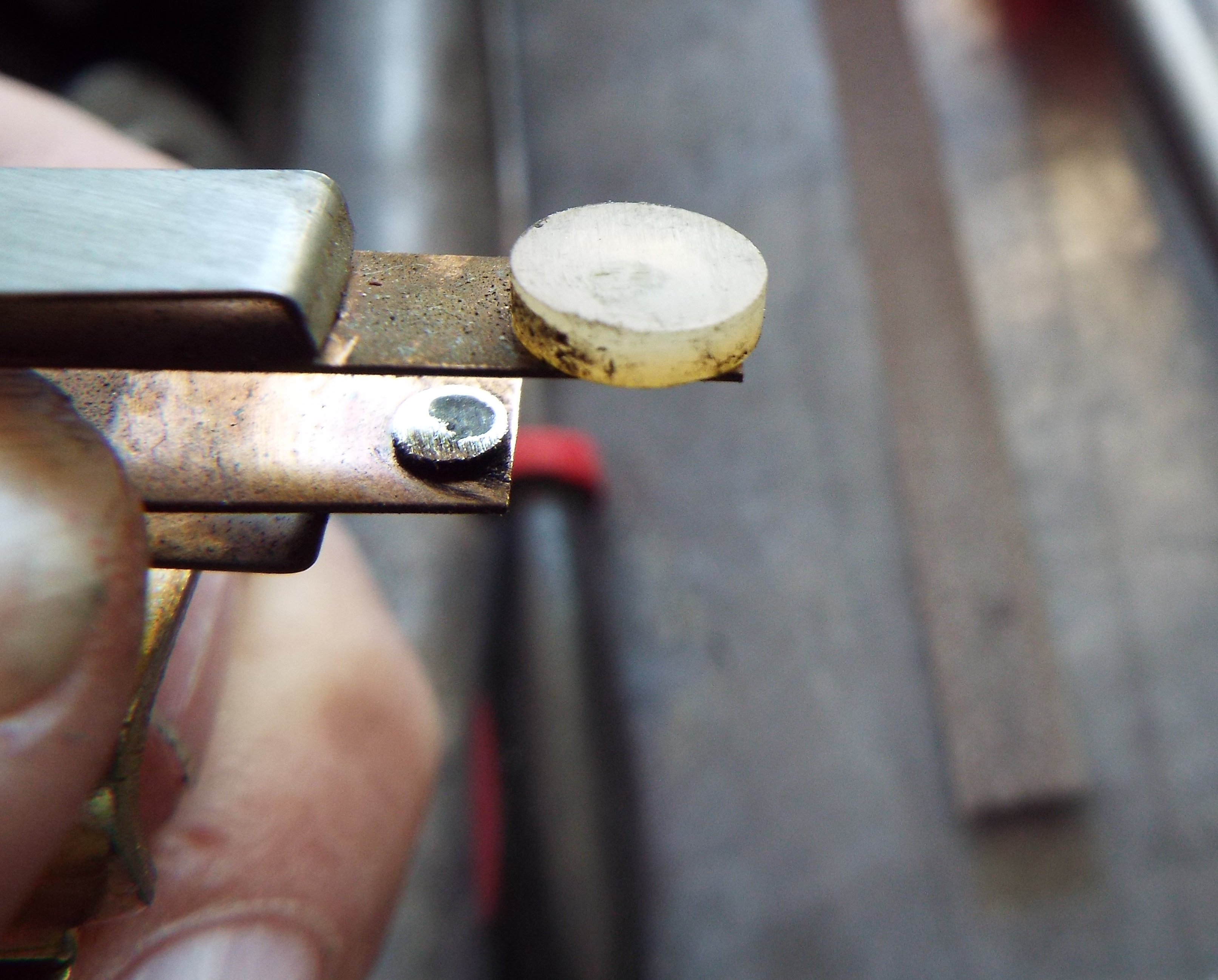
That first selection of 266 resulting in selecting 244 was all I needed. No need to pick several more selections. I had a problem. First thing is to pull the black and gray boxes and test them on the STD4 test box. Tried 266 first and nothing. Selected some 100’s and they played. So, no 200’s. It’s tough when the test jukebox starts misbehaving. Put the originals back in-no 200’s. Pulled the contact block, both wires in place for A or B side selection. Cleaned the contact block points out of habit. Double-checked the vertical and horizontal adjustment. NO 200’s. Will it pick up anything? Yes, still picking up 100’s. Dove deeper into the contact block and the right side actuator screw was not hitting the contact block enough to switch it fully up to make contact with the tormat. As a matter of fact it was screwed all the way in with no adjustment left as the screw head takes up a fair amount of space. Instead of installing a longer screw I just reversed the one I had with the screw head hitting the contact block and now had adjustment and selecting the 200’s. I put a nut on the backside to hold it tight. In fact all selections were now being properly picked up. The STD3 black and gray boxes are good.
Pulled the STD3 DCC boards one at a time and tested them. I started getting one-off selections as in 123 played 124, 147 played 148. Back to original boards and same thing. Turned out the STD4 tormat needed just a hair of adjustment-messing with the actuator screw I had gotten the tormat out of position slightly. So, I triple-checked all the tormat adjustments and got it properly aligned so that the mech picked up “the corners”, selections 100/200 and 179/279. Back to business at hand. Put all the STD3 stuff into the 4-black and gray box and all three boards. Wanted to see it all work together. Now, this all occurred over a period of several days. Of a sudden no Selection Playing indicator lights. Oh no, I must have blown a fuse-probably one of the components from the 3. I had to stick them back into the 3 to see that I had Selection Playing indicator lights there so something wrong with the test juke… again.
First step is to check voltages and to that end the question is what supplies the lamps for that circuit? Broke out the schematics. Seeburg didn’t make it easy like it was a M100B manual. No, the STD series comprises four different smaller manuals. I had to pull out manuals and folders and saved page scraps to find all this. Turns out it is F3104 a 15A fuse in the Digital Control Center for 25vac. Fuse good, I checked the cable-side wire on J3101 Pin2 on the DCC and had no voltage. Starting at the fuse with one lead grounded I chased the voltage to the back side of J3101 to an orange wire and had voltage. But not on the front side. Unplugged the cable and checked the pins. Pin2, the orange wire, was pushed in away from the plug. Remedied that real quick by pulling the pin, spreading the tangs out, and re-inserting. Now all the DCC boards and both boxes were giving correct selections on the test juke. I must have a wire problem on the STD3. Oh, the horror!
Indeed! Wire problems are the worst. It could be anywhere and there are so many wires. I had a few things going for me though. First, the problem definitely had to do with the four lines (and thus wires) of code used by Seeburg to write in a selection. These originate at the DEC or Digital Electrical Selector or keypad and go to the black box, to the buffer board in the DCC, and then to the gray box that actually writes in or charges the individual dots on the tormat.
The second factor in my favor is that wire problems are almost always at one end of the wire or the other-the contacts and connections. Middle of the wire problems so to speak are usually due to physical damage like getting pinched, shorted, or accidentally cut.
OK! I started a long tedious process of using my ohmmeter and testing these four wires from one component to the next for continuity meaning there is an unbroken wire from one end to the other. I did have a handy guide from one of Seeburg’s check out procedures handouts. But, I spent considerable time getting plug and pin numbers from schematics to plug into that illustration to be able to check wires with the confidence needed. In troubleshooting, jukeboxes or anything else, one must be confident at each step of the way that one eliminated a problem source before moving to the next possible cause. It took hours but long story short all the wiring checked out. I did not check the DCC internal chassis wiring. It’s always good, right? Now I was getting desperate. I have seen crimped on molex connectors over time and usage get loose enough to actually create an open at the terminal or pin. So I “shotgunned” pin replacement on two of the DCC’s plug and jack connectors, J3101 and J3104, that each held the four wires the code ran on. “Shotgunning” means to just replace something without really testing in the hopes that much like a real shotgun pellet blast I’ll hit something. Sometimes it’s a time saving measure, sometimes it doesn’t work at all. But I did have peace of mind that a loose connector was not the problem. Peace of mind with wiring problems comes at a cost.

Now I’m thinking that my wire problem must be somewhere in the cabling. This is a true horror. It could be anywhere. I was able to take the whole keypad panel cabling and all off of the STD4 and try it on the STD3. That didn’t change a thing. Once again I was using the quick 266 selection to see if the problem still existed. For the heck of it and because at this point I was still clueless I started making all kinds of selections to see what happened. If I picked 200 then 211 played. Pick 211 and 200 would play! Pick 100 and 111 would play. Pick 111 and 100 would play. 110 gave 101. Oddly enough 122 actually picked the correct one. 130, 140, 150, 160, 170 all played one up as in 131,141, 151, etc. It was not tormat position, believe me. I actually put records in both spaces such as 140 and 141 so I could physically see that the rack wasn’t off somehow.
I turned back to this sixteen page checkout procedure handout from Seeburg. It has a LOT of neat tests that allow one to hopefully pinpoint a problem. The neatest was the fact that using a test lead inserted into the proper pin at the external DCC plug and scratching the other end against ground I could make selections. Of course it says that if these selections play change that, if those play, or don’t play, change this. It all boiled down to the same stuff I originally tested. Black and gray boxes, and all three boards in the DCC with an occasional “replace the tormat”. Oddly enough, Seeburg made a tester for the route technician that duplicates these tests much more quickly. I’ve had a couple of them.
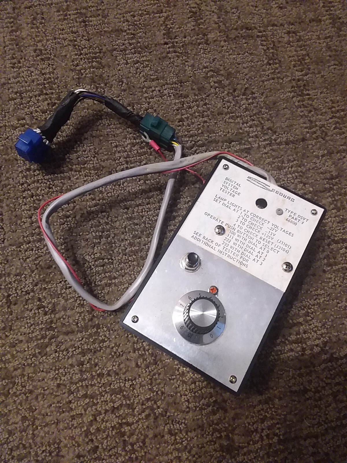
Stuck in the belief that I had a wiring problem somewhere in the cabling I examined that cabling between components. Could I remove a cable from here to there from the STD4 and try it on the 3? NO. All the cables intertwine so much that I would have to take it all out as one piece and that IS A JOB. I spent a couple days letting this stew, trying to figure out the next step.
It occurred to me that I had another STD3 sitting in the garage, the one I brought from Texas. I was told it was working except for the amp when I bought it. Indeed, I had actually done electronic repair on it for the guy. If I couldn’t swap cabling I could swap out the whole box. So I verified that this STD3 was working correctly and it was! The next day I swapped out the whole mechanism, the black and gray boxes, and the complete DCC unit from the STD3 to the Texas box. Got it all connected. Selected 266 and it played 244!!!! I quickly pulled the tormat from the mechanism and swapped in the tormat from my STD4. This time I practically quadruple-checked the adjustments and such. Same thing, select 266 get 244. OK, not the tormat. Damned sure not any of the boxes or boards so it must be in the DCC chassis. I had never swapped out the complete DCC until now.
I got all excited. I got this isolated at last! I started pulling out all the manuals and papers anew just in a tizzy. Yes, googly-eyed and running in circles. Then common sense prevailed. I got another DCC from the shelf. Turned them both over next to each other and started looking at wire colors to see if they matched. It didn’t take long to see that a couple wires on the buffer board edge connector didn’t match and then to notice a small repair a previous super tech had performed. I’m guessing that the intention was to replace a couple of broken or flattened pins in the connector. These aren’t regular molex connector pins. I had quite an argument with an “expert” over this one time. Seeburg used what are now called aviation pins, um….used in the aviation industry, and sell for about 3.00 each. Check ebay. No, frugal me has taken many many pins out of scrap edge connectors leaving 2-3 inches of wire to splice to. This is what this fellow did except he got pins 3 and 8 ass backwards. And you can see the tiny heatshrinked splices. So small I overlooked them. These are Data D and Data C lines respectively. It took me a couple minutes to swap them to their correct position and now the jukebox selects correctly, problem solved. If anyone ever wonders how I learned what I have over the years it is because of issues like this be it mechanical or electrical where I’ve had to spend hours tracking something down diving deeper than anyone would seemingly have to in order to find a problem.