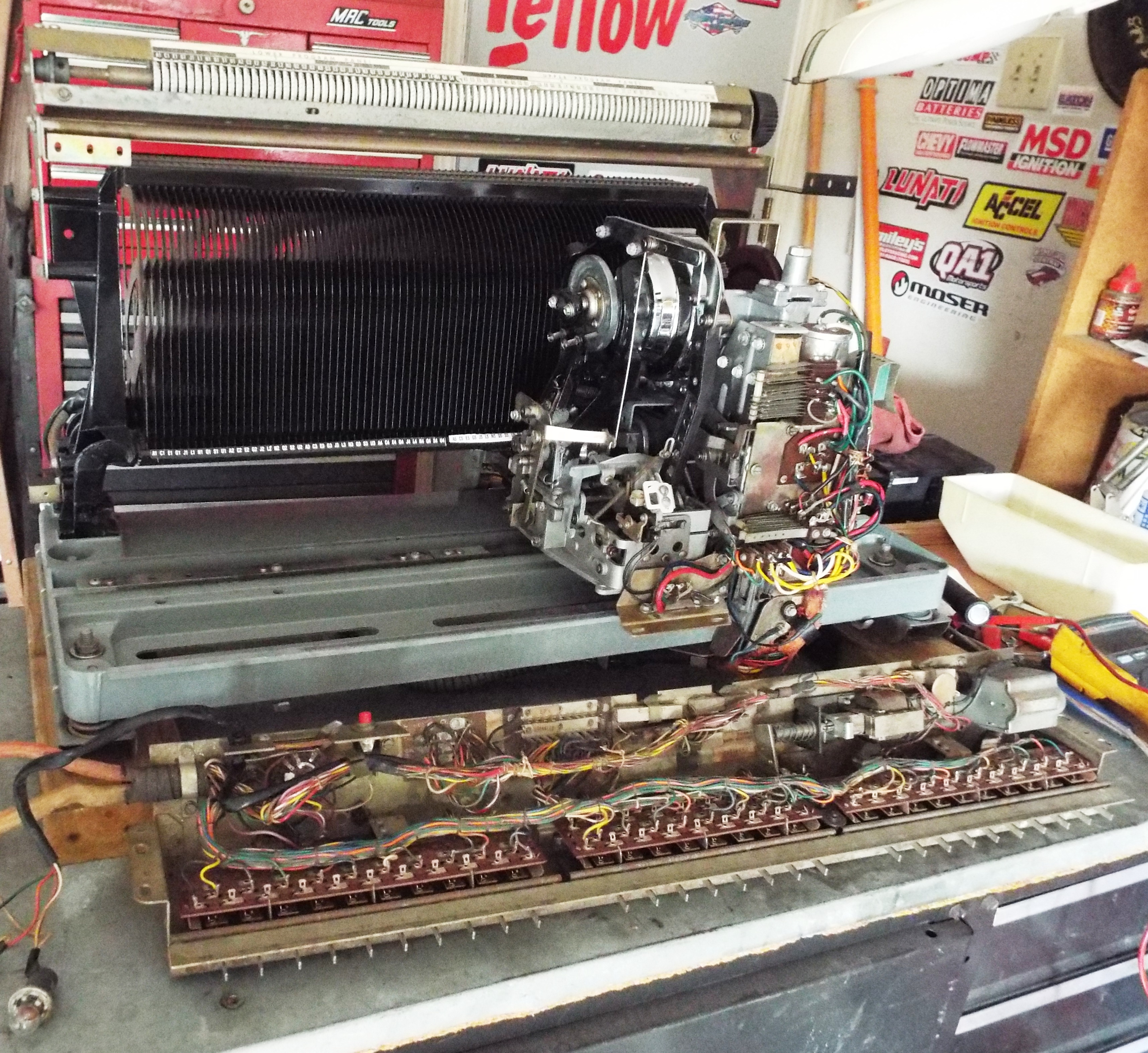
Worked on the 6000 mechanism this afternoon to change out the scan motor gear set. It went way smoother than usual. Take the two belts off, remove the turntable assembly, remove three screws holding the sideplate on, turn the motor so that the clutch assembly blade is turned just so, remove the three screws on top actually holding the motor in and wiggle it out! I removed the top to the case and took out the gears. I expected the big gear to have busted another tooth but that wasn’t the issue. The small gear had teeth sheared by the metal worm gear. I could have put another small gear in it but I wanted to try this set Larry sent. It looks superb!
The big driven gear has a metal shaft going through it with a spring held in place by a tiny roll pin. The shaft installs from the bottom of the gear and the spring keeps it against the shoulders. Hard to explain and of course I didn’t take pictures. I got the shaft out of the old gear and installed in the new gear in about five minutes. I cleaned the case out, re-greased everything and put it back together. I will run the mech tomorrow and check the gears.
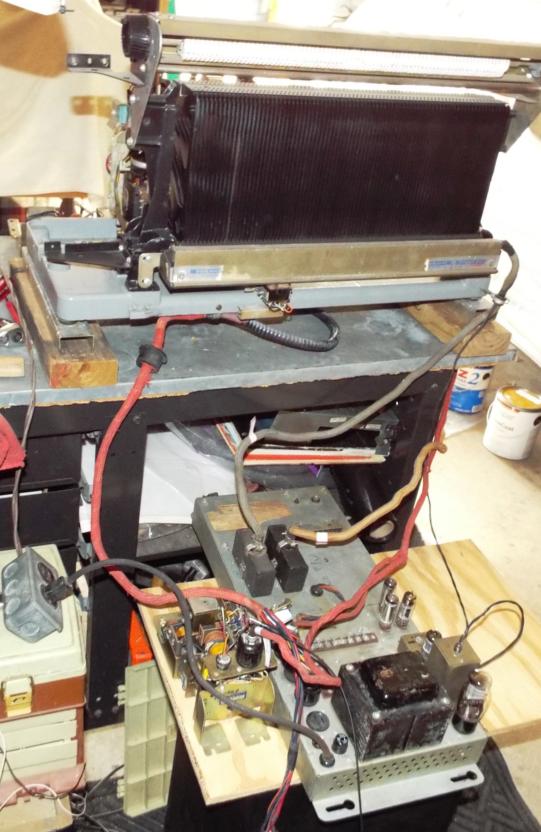
I’ve been thinking though….this isn’t the first gear that has experienced shear from the metal worm gear. Seeburg had these mechanisms suspended above the cabinet bottom hanging by rods and springs. If anyone has heard these mechs in operation there is quite a bit of swinging movement when the mech changes scan direction. Quite a bit of noise when 50 albums rattle as well. I have a sneaking feeling that Seeburg did it to absorb some of the shock when the mech changes direction. Without this shock absorbing the small gear can get sheared. I felt this so much that I asked Scott, the guy in New York who bought the HSC1 assembly from me, to hang his just in case. He had sheared a gear less than a week after getting it from me and had it resting on a couple pieces of wood like I do now. (Scott is a Jukebox Hero for sorting out all the problems he had with that danged thing) He had a custom cabinet made for it. I had made sure to include the hangers and springs so that the mech could be hung as originally intended. He had that done and hasn’t had any problems from the gears since. I’m thinking it might be a good idea to rig some kind of framework on the bench to hang my mechanism from. I have the hangers and springs for it as well. When I originally stripped these cabinets way out in the Piney Woods I made sure to get all of this hardware. All told I think my mech ran less than 4 hours when this latest gear sheared.
Tracy, the fellow with the 222 receiver, amp, keyboard, and mechanism brought more 222 items when he picked up the first load Sunday. I wouldn’t let him bring the mech this time. I need the bench space for the 6000 album player. I finished up the evening ‘shift” by doing preliminary work on the SHFA1 amplifier. I replaced the 15 amp fuse in it with a properly sized 5A. When I was in business doing repair and restoration I never had to buy any 15, 20, 25, or 30 amp fuses. I just kept the ones customers installed when their original fuse blew for whatever reason. Anyone who wants to know….the fuse amperage is engraved on on end of the fuse cap. It’s always printed by the fuseholder as well. A lot of damage can be done by overfusing. Anyway, I learned the hard way to check AC voltages to ensure a good power transformer. It’s a bad feeling to recap one of these amps only to find out the transformer is bad. It had good 5vac heater voltage and 1006vac on the power side! The first time I saw this high an AC voltage I was stupified. I spent a long time researching and finally came to the conclusion that no load AC voltages are just way on the high side. The SHFA1 and 2 are the only amps I’ve seen with this high a no-load AC voltage. Once recapped the B+ DC voltage will be under 500v like it’s supposed to be.
As a side note replacement transformers can be had for power and output but the cost of a new transformer plus the labor to install it is way more than buying another amp and starting with a good original transformer. Same for the receiver. Unless it’s a rare V200 TSR1 or 3. I swapped a lot of TSU transformers into TSR1’s and 3’s back in the day. Ask Walt B. The V200 King. For a short time someone actually made replacement transformers for the TSU which will retrofit into the TSR. That was back in the 90’s. I do have one. I recognized it instantly when I found it on the shelf in an operators’ warehouse. It’s large and has many many windings. One day I’ll sit down with it and get them paired properly.
I put what I thought was the TSU1 on the table and quickly found out it is a TSR6 from a 161/201. I gave Tracy a call and told him he has the wrong receiver. He said, “Well it worked in the 222. Funny though, the only way I could add credits was to use the service switch push button.” I gently told him that the keyboard assembly, receiver and credit unit all have to match and since it didn’t that was why he had to use the pushbutton to get a credit. A lot of boxes will work with single or dual pricing units but still have to have the capability to match it. This matching was done at the electrical selector by switching wires to Single or Dual. He has a 201 so wants me to go ahead with the TSR6 for a spare. I quickly checked the 155vac and 325vac windings for correct voltage. These are the only ones that ever blow. They were good. I have a TSU1 I recapped that ironically I tested using his gear. I’ll let him have it and a SPU credit unit that’s been reconditioned and tested for a fair price. All problems solved, everybody happy.