Re-Inventing The Wheel
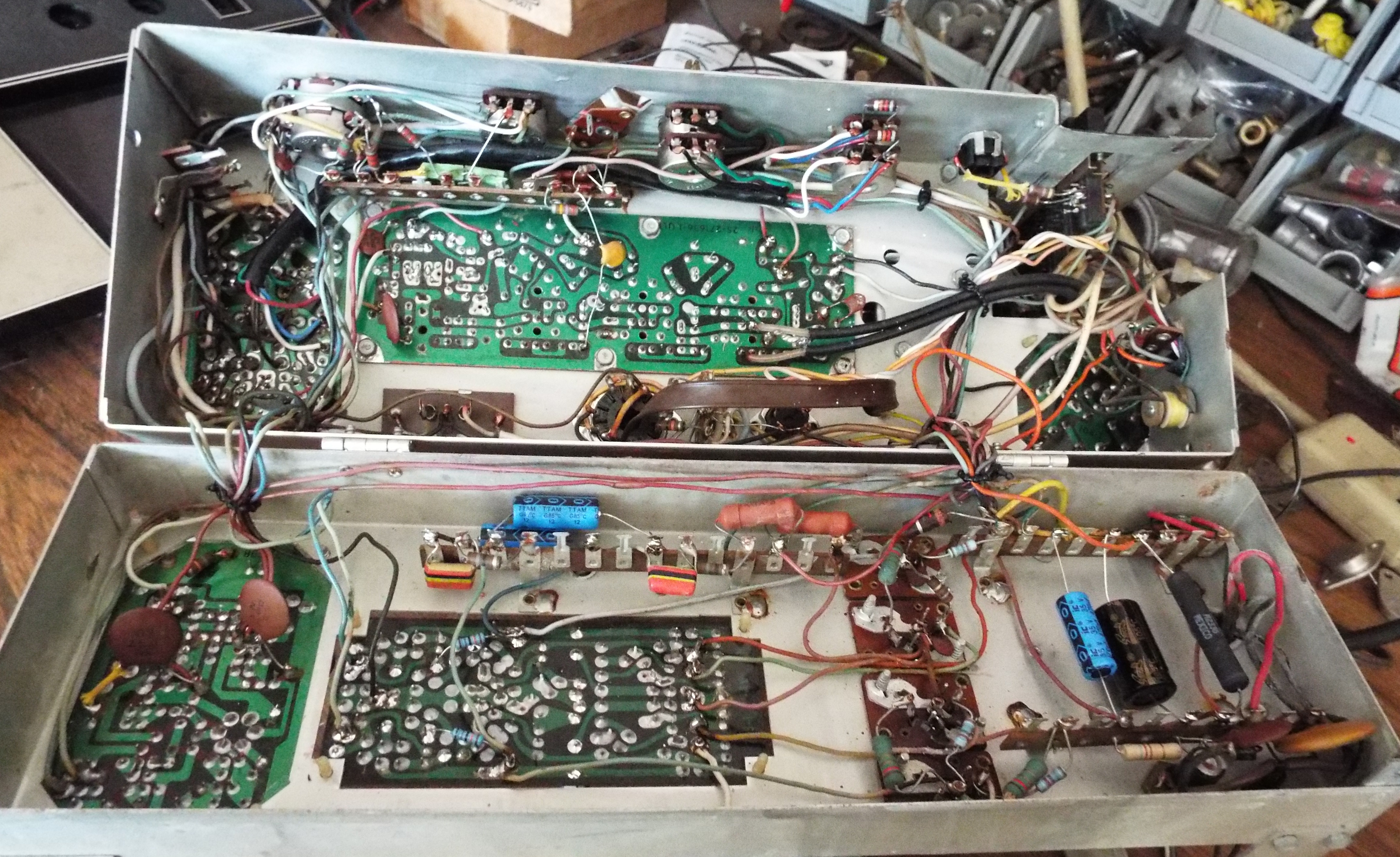
Seeburg has been pretty consistent with their parts. Most of the electrical and mechanical parts, especially the mechanisms, follow a logical step forward as technology improves. The basic mechanism has been the same from 1950 to 1984 with minor electrical and switch changes and major changes such as losing first the pinbank in 1956 then the tormat in 1978. Its consistency has been one of the pleasures of working on Seeburgs. In fact the first manual I got and continually refer to is the one for the 1950-51 M100B. Since the 100B was the introduction of the 45 rpm mechanism Seeburg went all out with explanations, flow charts, and diagrams. Occasionally some engineer seems to have to prove he can re-invent the wheel. Witness the 1963 LPC1 jukebox. Its mechanism will pick up records in one direction of travel only. The clutch was cut differently so that the mech could literally not return to scan should it somehow trip going from right to left. Seeburg gave it one more year-the LPC480 before giving up on that mess.
One of the consistencies has been the reversing switch. The one with the big paddle front and center as low as you can go on the mechanism. It started out with four pairs of switches. With the disappearance of the pinbank it went to three pairs of switches and then finally to two pairs of switches with the microlog jukes. The two pair being the 115vac to the motor that has been present in all the reversing switches. But apparently some engineer saw a chance to prove he could re-invent the wheel yet again. Witness the reverse switch for the 6000 series of home consoles.
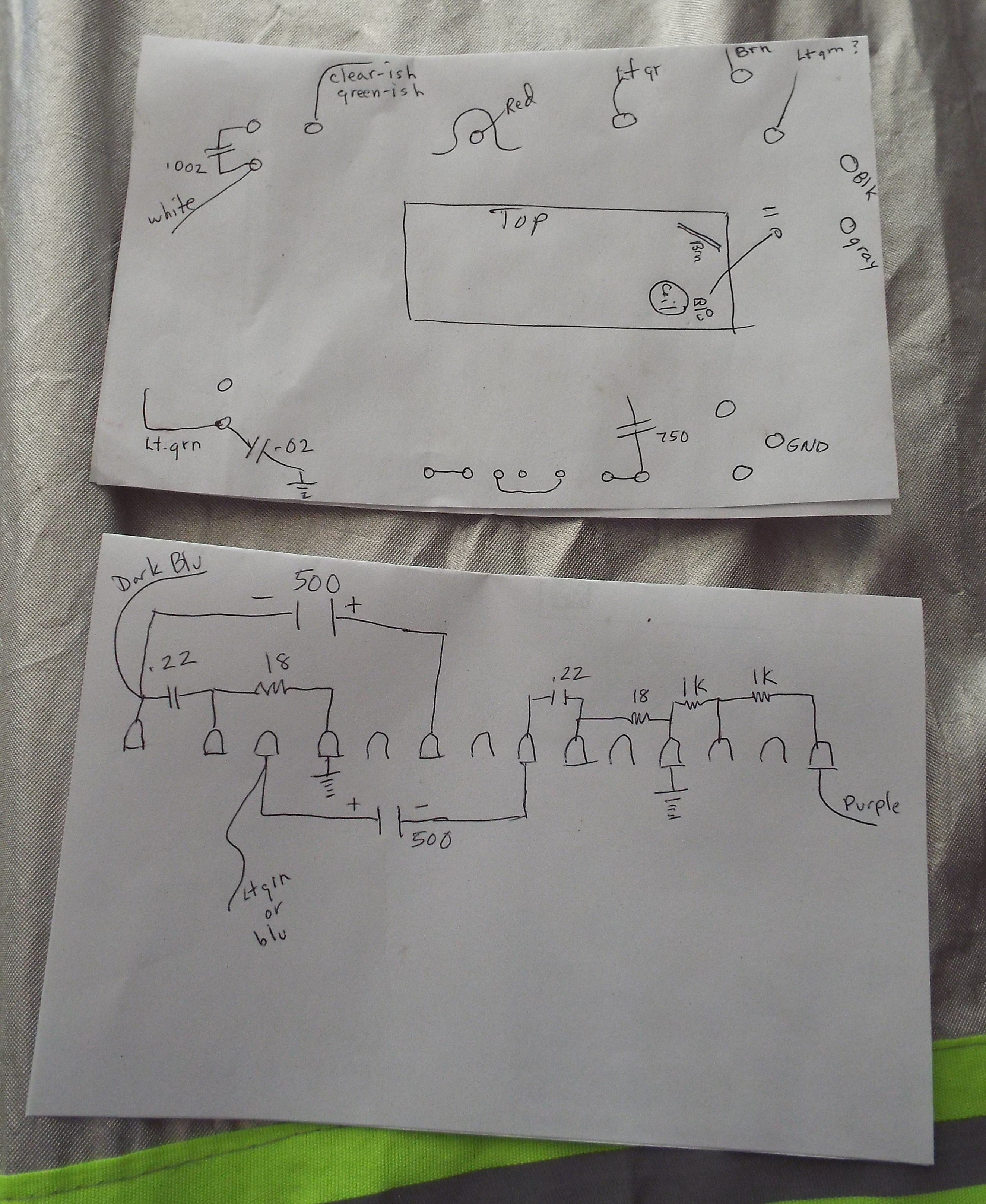
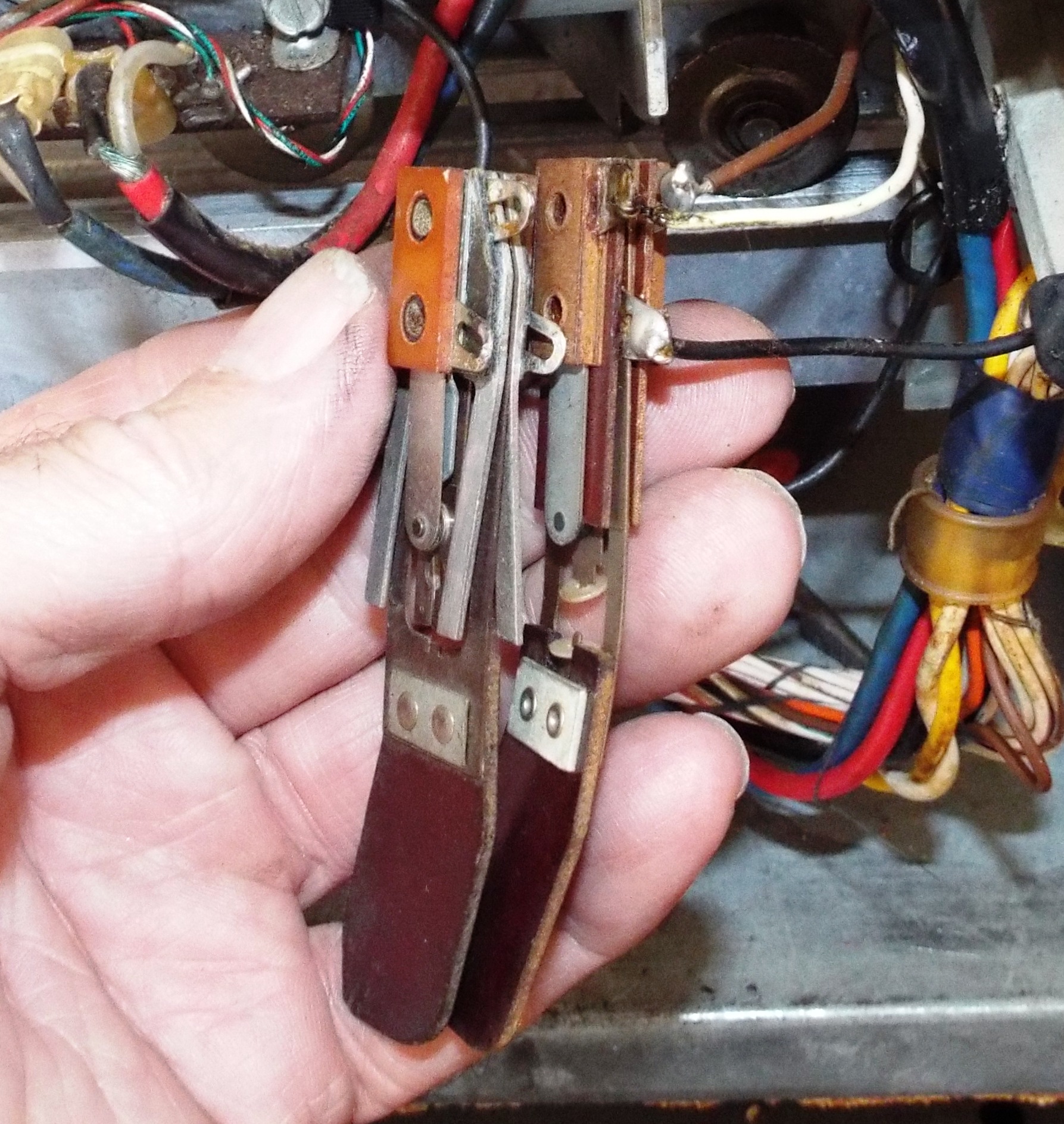
I was poking around on this 6000 album player and noticed the reversing switch looked unlike any I had seen before. It consisted of only one set of switches and was obviously missing a spring. A spring unlike those seen on a reversing switch before or since. I had no idea if that spring came off since being in my possession or possibly it was the reason the 6000 got put away. I gave a cursory look around the bench more out of habit than hope for the spring. However, the spring may have been funky but it was still a reverse switch. I have a box of these taken from scrapped mechanisms over the years and dug out a nice two-pair to convert to use on the 6000.
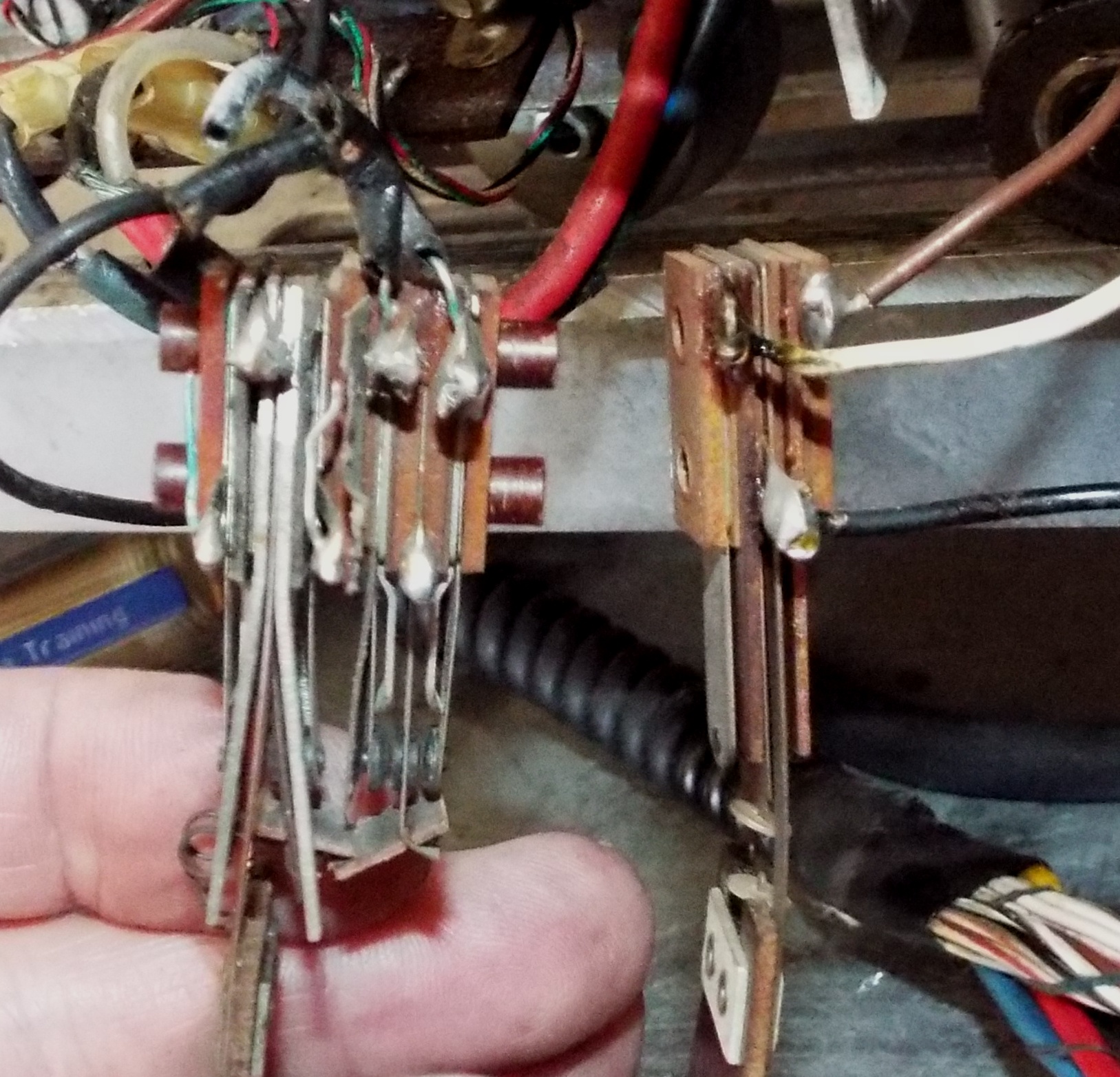
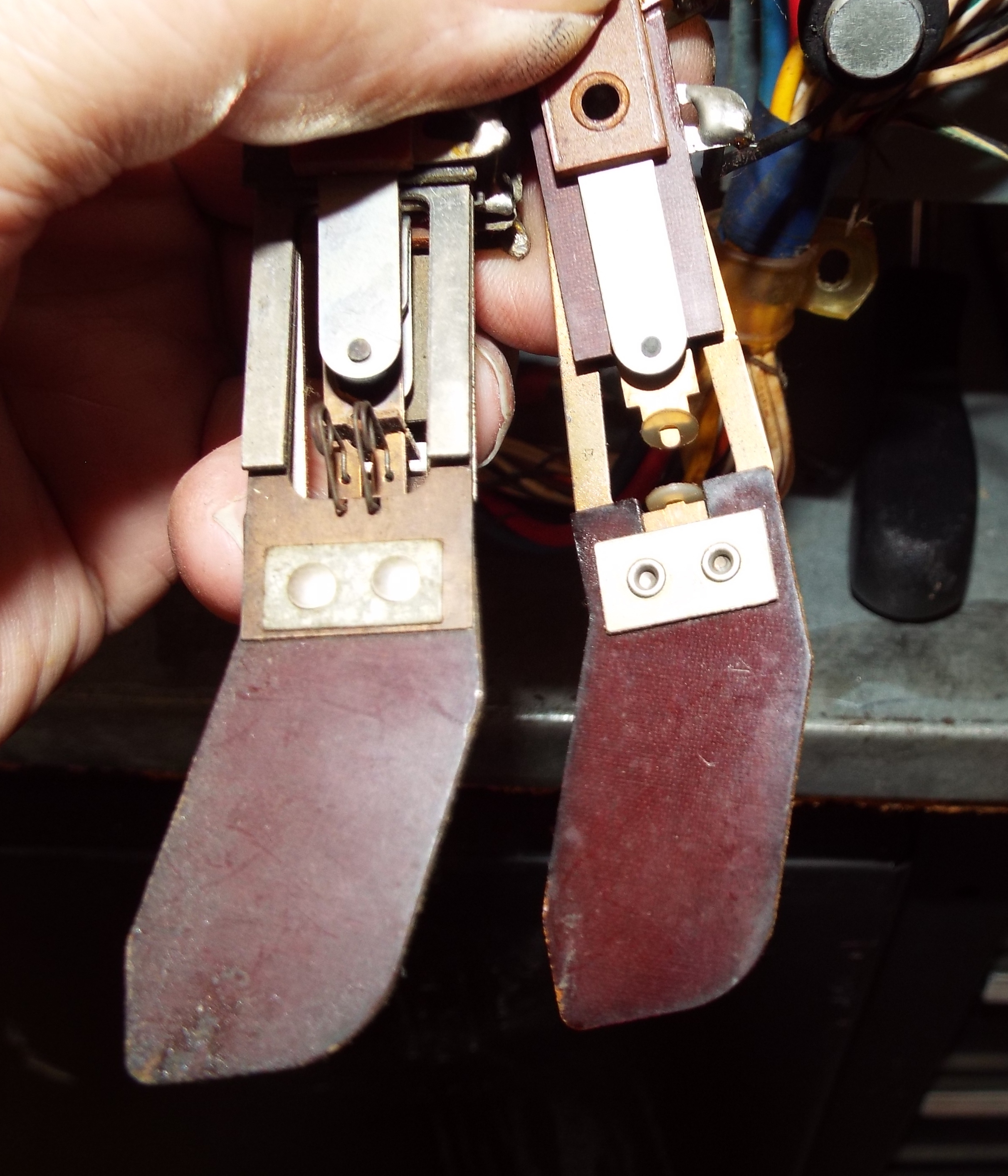
I’ve replaced broken paddles and broken contact blades on many reverse switches over the years. It becomes fairly critical on the four pair switches used on the 100 Selects as even good used ones are fairly difficult to find. Amazingly, NOS ones come up now and then. The thin fiberboard or bakelite actuator is so fragile on any of these but especially the four pair. These switches are put together using two small cylinders to hold all the various bakelite spacers and metal contacts together. I use a somewhat dull pocket knife to get between the spacers and work each piece off. I don’t use it to cut at all but the knife edge works well at getting between the pieces. It’s basically a matter of keeping everything in order.
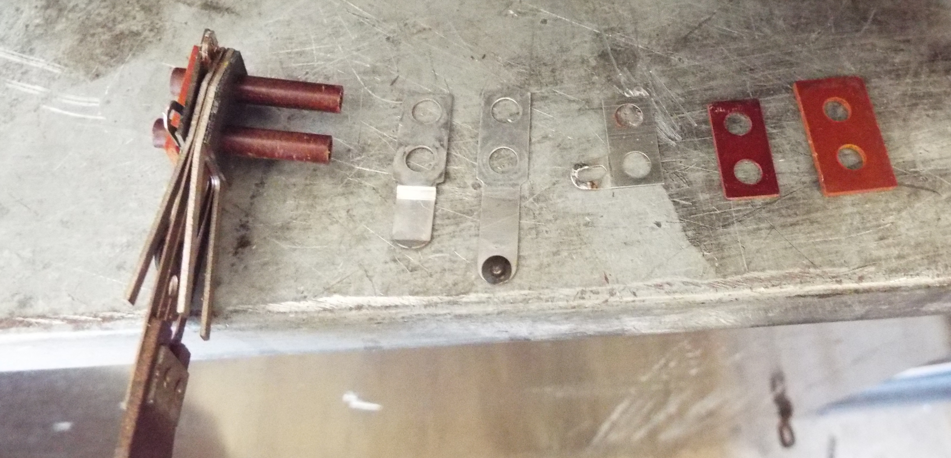
I kind of like this type of work. It’s something different and a challenge to be able to fashion something to take the place of a seemingly irreplaceable part. One set of contacts would work for the 6000. I wanted to get it the same size or thickness as the original as it mounts to a metal piece screwed to the mechanism. Once I got the reverse switch pared down to size I trimmed the two hollow stems with a Dremel and cut-off wheel and re-stacked the pieces. I made sure to clean the contacts when I had them off. Once put back together the switch was the same thickness as the original and switched perfectly. It was then a matter of soldering the three wires to their respective spots.
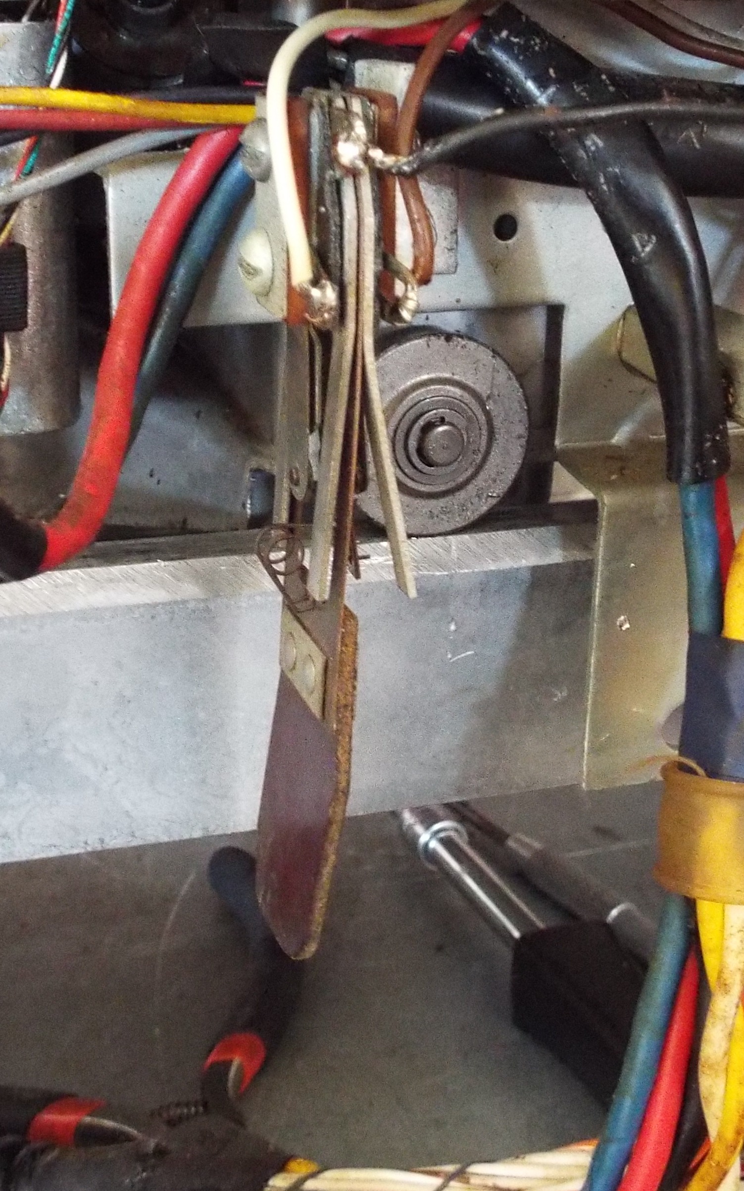
And of course I got my comeuppance. After successfully making a replacement reverse switch and mounting it I tested it by manually switching it as the mechanism ran. It dutifully changed direction back and forth so I let it run the width of the base. BAM!!! It went all the way to the left end and hung. The new switch paddle did not have as much inward curve as the original and scooted right by the actuating tab. You would think this is something minor but NOOOOO. I had broken a gear on the HSC1 this summer by trying to force the mechanism and had learned my lesson. Using the T shaped tool to move these mechs with it wouldn’t budge.Not gonna force it, gotta save the gear. I would have to somehow get the clutch loose enough that I could move the mechanism without it catching the geared track. The only way to do this is to loosen the clutch. I really didn’t want to take the tormat and record rack off. I had spent a lot of time aligning them. I somehow managed to loosen the four clutch mounting screws and managed to move the mech enough that the T tool would work.
While I had the clutch loose I bent the left and right actuating tabs out to hit the new reverse switch paddle and double-checked by moving the mechanism by hand. After tightening the clutch I then applied power and watched it run back and forth. I was extremely grateful I had not broken the replacement gear. And very pleased with the new reverse switch.